
2B1 Solve series / parallel resistor circuits to calculate
currents, voltages, resistances and power given appropriate values.
This may include the use of series/parallel formulae, Ohm's Law and power.
Equations include P = V2/R and P = I2 x R
Resistors and what they are, were introduced to you in the Foundation Licence course and developed in the Intermediate Licence course.
There are two quite different, and for some of you reading the course, challenging formulae associated with resistor combinations whether they are in series or in parallel. So let us remind you about them.
The diagram below shows resistors connected in series.

For a calculation any number of resistors, (from as few as two) may be connected as shown above.
The effective resistance of the combination of R1 R2 and R3 is given by:
R(total) = R1 + R2 + R3
BUT you can of course add together as many resistors as you need to and calculate the total effective resistance of all the resistors.
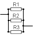
The diagram below shows resistors connected in parallel.

Note that all the resistors are linked to each other by the wire that is across the end of of them all so it does not matter where the other wires connect to the circuit the result would be the same.
For a calculation any number of resistors, (from as few as two) may also be connected as shown above.
The effective resistance of the combination of R1, R2, and R3, is given by:
![]()
which can also be written as :- 1/R(total)= 1/R1 + 1/R2 + 1/R3
BUT as with the earlier example you can of course add together as many resistors as you need to and calculate the total effective resistance of all the resistors.
Let's put in some values. R1 = 100 ohms, R2 = 150 ohms, R3 = 270 ohms
Thus 1/R(total) = 1/100 + 1/150 + 1/270
so 1/R(total) = 0.01 + 0.0066 + 0.0037
so 1/R(total) = 0.0203
so R(total) = 1/0.0203
so R(total) = 49.26
So the total resistance of R1, R2 and R3 in parallel is about 49 ohms
Note:- that the resulting resistance is always less than the lowest resistor value in the group.
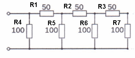
However consider what would happen in a mix of series and parallel.. we have to take a stage at a time because of the complex calculations required. This is not impossible, just follow it slowly, one step at a time.

Looking at R3 and R7 they are linked in Series so total value is
150 Ω - call that R8 (100+50=150)
Now look at R8 and R6 they are link in parallel so total value is
now 60 Ω - call that R9 (parallel rule)
Now looking at R9 and R2 - they are linked in Series so total value
is 110 Ω - so call that R10 (60+50+110)
now looking at R10 and R5 they are in parallel so total value is
52.38 Ω - so call that R11 (parallel rule)
now looking at R11 and R1 they are in series, so total value is
102.38 Ω - call that R12
now we look at R12 and R4 in parallel, total becomes 50.5 Ω
(with the parallel rule) we get 50.5 Ω. What a lot of work,
six steps, but we have completed it now.
For the exam do the calculation as shown and then compare your answer to that in the question and you will see what figure is like yours, and pick that as the correct answer.
If you are weak on maths then ask your lead instructor for some extra work on this to help you learn it.
Understand and apply the formula relating power to potential difference, current and resistance.
The formulae are :-
which can also be written using the mathematical notation of placing two letters together meaning multiply them together as:-
Now the formulae are :-
In the Foundation Licence course you were introduced to two magic triangles, one relating to power, potential difference and current (P = V x I), and another one relating to potential difference, current and resistance (V =I x R). The triangles were again used in the intermediate Licence course.
Now we are going to develop your knowledge further and see what can be done with the two formula and a little bit of mathematics which either you may have forgotten from school or may not even have learned yet.
If you look at the two formulas you will note that there is some similarity in that both have V and I.
We can therefore mathematically substitute the V in P = V x I
 by the V = I x R
  and we would get :-
So from the original equation P = V x I
we can substituted the V by using V from the equation V = I x R by the I x R and the result is
P = I x R x I which could also be written as <
P = I x I x R so we can progress further and say
I x I = I2 which is I times I which equals I squared and is written as I2
thus P = I2 x R
which was the last formula in the syllabus section, so what about the other one?
well from V = I x R also we manipulate the formula to give V / R = I
With the I is substituted by V / R in P = V x I
we get P = V x V / R
thus P = V2 / R which is the other equation mentioned in the syllabus.
So you do not have to actually have to learn
P = V2 / R and also P = I2 x R
assuming that you can derive them from the two basic formulae of
P = V x I and also V = I x R
and now at least you now know where they come from !!!
2B1 Two or more resistors can be arranged to act as a potential divider and apply the formula
The formula is :-
![]()

Potential Divider
When a connection is taken from the junction between two resistors in series this is know as as fixed potentiometer or potential divider.

Note that R1 is nearest to the Positive + rail and R2 is nearest to the Negative - rail.
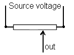
With the two resistors in this configuration a voltage somewhere between the maximum and minimum would be measured at the point marked "out" depending upon the values of the resistors. This fixed combination is usually replaced by a single resistor in which the output can be changed by moving a slider along the track.

The output could be taken from anywhere along the resistor.
Without necessarily knowing it you have all used such a potentiometer on the audio gain control on your transceiver / receiver !!!
Potential divider formula
However a potential divider can be two or more resistors but what ever number it is the resultant formula would be
![]() as we would have to do separate
calculation to end up with two resistors.
as we would have to do separate
calculation to end up with two resistors.
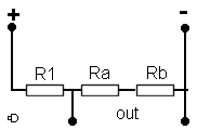
Looking at the diagram, 
you can see that the output is leaving the potential divider of R1, Ra and Rb at the link between R1 and Ra.
With Ra and Rb are in series we can simply add together their values
and come up with R2. This R2 we can use in the formula ![]() ........ simple eh ??
........ simple eh ??

The Vout is thus dependent upon :-
Example if Volts in are 12V, R1 = 10 ohms, and R2 = 30 ohms, then
Vout= 12 x 30/(10 + 30)
Vout = 12 x 0.75
Vout = 9V
In order to make sure we use the correct power rating
of resistors we need to calculate the power in each resistor.
This very much depends on the load on the out side
of this circuit. But in this example, we are saying there is little
or no load as we are using the out voltage as a reference voltage
for use in calculating power ratings in this example,
so for resistor R1 we use P = V2/R...
we know that R1 voltage is 12 - 9 = 3V.
so V2/R = 3 x 3/10 = 9/10 watt (or 0.9W). We can
now say that R1 needs to be rated at least as 1 watt.
Similarly for R2:
V2/R = 9 x 9/30 = 81/30 = 2.7W
so we would need
at least a 3 watt rated resistor to fulfill this task.
Can you calculate the current flowing through each resistor? The answer should be the same for each. Try using the simple equation V = I x R from the magic triangle manipulated for the current. It should now read I = V/R. What is your answer?
The origin of some of the text on this page is from the RSGB with additions by the web master