|
|
|||||||||||||
|
|
|
||||||||||||
|
|
|||||||||||||
|
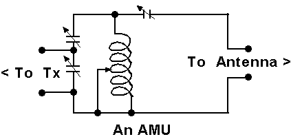
Syllabus Sections:- Antenna Matching Units 4F1 34 Understand that AMUs (ATUs) can cancel reactive components of the antenna system feed-point impedance (before or after the feeder) and can transform impedances to an acceptable resistive value. The main purpose of an ATU is to present to the Transmitter at its aerial socket a resistive load of the correct impedance. You are aware that an AMU (or ATU same item) does not actually tune the antenna, that can only be achieved by altering the physical dimensions of the antenna. What can an AMU achieve ? The AMU as this level of amateur radio prefers to use :-
How does it work ? In side an AMU is generally one or two large coils that can be "tapped" and a variable capacitor or several variable capacitors. By careful manipulation of the "tuning controls", at a low power input from the transmitter but sufficient to be able to observe the changes to the control settings, the inductor(s) (coil(s)) can "tune out" reactive components of the antenna system feed-point impedance and transform impedances to an acceptable resistive value. As there are parallel tuned circuits in the AMU it can also filter out unwanted harmonics of the wanted frequency. Additional parallel tuned circuits can develop high voltages and high current passing through the components, so great care has to be taken in the selection of the capacitors so that they will not break down or "flash over" - the wire of the inductor also needs to be of a substantial size. Can an AMU tune all antennas ? Quite simply No !! Whilst you do not have to know
the ins and outs of exactly what are the limitations and how
do they come about - you do have to know that the AMU can
match a fairly wide range of impedance mismatches to the
usual 50
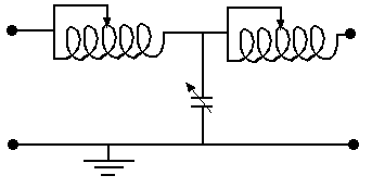
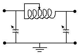
------------------------------------------------------------------------------------------------------------ 4F1 34 continued Identify typical AMU circuits (i.e. T, Pi and L circuits). The AMU can come in various forms T, Pi and L styles and you have to be able
to identify the types. If you look closely you will note
that the "T" type looks like a "T", the "PI" type like the
Greek letter "
You have to be able to distinguish between the various circuit diagrams.
|
|||||||||||||
|
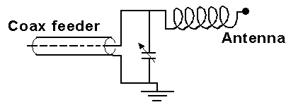
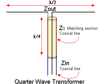
4F2 34 Understand that a quarter-wave length of feeder can be used as an impedance transformer. Apply simple examples of the formula Z02 = Zin x Zout The formulae for calculating the impedance of a matching section will be given to you in the exam, if a question on this topic comes up so the important points to know are what do the mathematical notations represent. Z02
= Zin x Zout
In the formula:- Z0 = the impedance of the quarter-wave length of feeder matching line Zin is the impedance of the feed line to which the antenna is to be matched Zout the impedance of the antenna. Note that the Z0 is "squared" so to find the answer as to the impedance of the matching section you would have to use :- all that we have done is "take the square root" of both sides, so as long as you understand such manipulation the result can be easily found. Example:- What would be the matching section's impedance to match a 75 ohms dipole to 50 ohms coax. Z0 = square root of ( 75 x 50 ) = 61.2 ohms.Now it is not very easy to find such a piece of coaxial feeder so what other feed line could be better used ? Twin feeder of course, but for the exam you do not have to go into how you would achieve the physical dimensions of the matching section just be able to calculate it - as a diagram of coaxial feeder is easier to remember that it why we have used it.
|
|||||||||||||
|
|
|||||||||||||
|
|
|||||||||||||
|
|
|||||||||||||
|
|
|||||||||||||


