|
||||||||||||||||
|
|
|
|||||||||||||||
|
|
||||||||||||||||
|
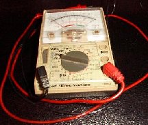
Syllabus Sections:- Measurement 9A1 54 Understand the use of series multiplier resistors in analogue voltmeters, shunts in ammeters Meters Analogue and Digital Despite the popularity of digital voltmeters (DVMs) meters with a numbers display, there is still a requirement for analogue meters with a moving needle display, especially in the Amateur Radio field, where we are often watching voltages/currents which are changing values, and, we may be looking, or "tuning" for, a maximum or minimum value. The
Analogue Meter relies upon a movable coil taking some current
from the circuit to create a magnetic field which then can
move the meter's needle relative to the stationary permanent
magnetic field of the meter against to pressure of a hair
spring. This does cause errors in readings when actual amounts
of voltage are being assessed but does an excellent job of
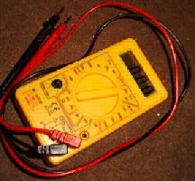
showing the maximum or minimum or changing voltages. The Digital
meter has none of these complex moving parts and does not
affect the circuit it is measuring. Thus this meter does an
excellent job of assessing actual voltages but is not good for
assessing varying voltages.
When looking, or "tuning" for, a maximum or minimum value, such operations are very difficult using a DVM as the voltage/current value is sampled at intervals with a hold delay between samples where as the analogue meter, due to its construction, the needle swings to show the valve applied. The analogue meter is used if you wish to detect a slow change in values which is not possible with the digital meter. Notice the dials on the front of each meter these are used to select the range of the display. For the analogue meter this is particularly important so that the meter needle is not driven hard against the end stop due to the measured voltage being higher than the range. Series Multiplier Resistors for voltages and Shunts for Current in Analogue meters The dial on the meter is a multi position switch used to select from a range of voltages or currents. These ranges are calibrated for correct Full Scale Deflection (FSD) by using series multiplier resistors for measuring voltages and shunt resistors for measuring currents. The values of these resistances are determined by :-
Measuring Voltage on an Analogue meter Note: Voltage is measured using the meter in parallel with the circuit under consideration. A 10V FSD VOLT METER Let's look at a typical example of an analogue multimeter. If we have a basic meter movement which has I (amps current) for FSD = 1 milliamp and R (Ohms) coil = 100 ohms. So what voltage applied to the meter gives the FSD. From V = I x R then V = 0.001 x 100 = 0.1 volts. Use of multiplier resistor Such a low voltage would not be measured very often !! So what can we do to make the meter read 10V FSD on say switch position 1 - use a series resistor which is called a "Multiplier". If we apply 10V to the meter without a multiplier resistor it would cause the needle to swing hard over and possibly break the meter. We know that 10V DC must cause a current of 1mA to flow through the meter for FSD, so we need to calculate what resistance will cause a current of 1mA to flow when 10v is applied. Using ohm's law V = I x R and ignore the meter resistance for the moment in this example !! re-arranged R = V / I = 10 / 0.001 = 10000 ohms or 10k BUT we have not considered the coil's resistance = 100R, and this would cause errors in reading. If we used the 10k we would have a total series resistance of 10k plus that of the meter 100R giving is 10,100R and therefore the calculation which gives the current I = V / R
Then 10 / 10,100 = 0.99mA through the meter and does not achieve the 1mA FSD - there is a 1% error. The solution is to subtract 100 ohms from 10k - thus 10,000 - 100 = 9900 ohms. This 9900 ohms resistor is the "Multiplier" which when added to the 100 Ohms of the meter gives us the 10K of the calculation above.. 100V FSD VOLT METER Similarly, if we require a FSD of 100V we must use a series resistance of R :- R - 100 = V(FSD) / I(coil) 100 / 0.001 = 99,900 ohms Two points to note are :-
Our Multimeter so far Note that the meter needs two scales 0 to 10 and 0 to 100 if you want direct reading. So lets look at an example of say 2 resistors connected in series say R1 = 220K and R2 = 100K and the meter with internal resistance of 100k ohms.  Assuming
10V across the Positive and Negative and using an analogue
meter what is the out put value. From the exam sheet we see
that :-
 So
plugging in the values Vout = 10 (100k / (220k + 100k))
This
gives a calculated result of 3.125V BUT this does
not take account of the internal resistance of the meter of
100k ohms.
As
we will be measuring with the positive lead on the output and
the negative lead on the Ground, you can see that R2 is in
parallel with the 100k ohms of the meter. The two resistors
will appear to as a value of 50k for R2 and thus the answer
when measured will be in error
Thus
doing the calculation we will find the error of using an
analogue meter on the circuit
Vout = 10 (50k / (220k + 50k)) so
Vout = 1.85 V when measured by the Analogue meter rather than
3.125V which was calculated but which did not take
account of the internal resistance !!
So
this does make things a little more complex than
the question might have looked !!! Measuring with an Analogue
meter ( a moving coil meter will draw current from the circuit
and cause an incorrect result to be measure by comparison to a
calculated result.
Digital
meter are thus devoid of such errors and thus ideal for
measuring stable voltages BUT cannot easily show changes in
voltages when trying to find a maximum voltage.
Measuring Current See  page 96 and onward regarding
"Alternating Currents and voltages" page 96 and onward regarding
"Alternating Currents and voltages"1 amp range Note: Current passing is measured using the meter in series with the circuit under consideration. Let's say we want to measure a DC current of 1 amp flowing from a 12V battery to a 12 watt lamp. We are using the same meter as before so there must still be only 1mA through the meter ANY MORE and we "can destroy" the movement!!! Shunt resistor Thus we must divert 999 milliamps past the meter movement! This time we use a "SHUNT" resistor across the meter movement - in parallel with the meter - BUT of what value ?? What is the voltage between points A and B through the meter coil? 1mA in 100 R, gives VAB= I x R = 0.001 x 100 = 0.1 volts Now in Rshunt I = 999mA and the V = 0.1 volts ( the voltage is the same as the resistors are in PARALLEL ). therefore Rshunt = V / I = 0.1 / 0.999 = 0.1001R NOTE:- The higher the current range, the smaller Rshunt becomes. These resistors, which carry HIGH CURRENTS, are normally made from resistance wire such as "Constantan wire", or even copper bus bar ( a thick piece of copper ) for very high currents. If you unsure about current value, always start with highest range and switch down the ranges as required. Meter sensitivity The quality of a multimeter is usually quoted in "ohms per volt". If we look at our example above, on the ten volt range we have input resistance of 10k, which we can say is 10k ohms per 10V which equals 1000 ohms per volt. Similarly, on the 100v range, the input resistance is 100k. 100k for 100v gives the same 1000 ohms per volt. Our meter sensitivity is 1000 ohms per volt, pretty poor, when a good "AVO" is 20,000 ohms per volt. Our Voltage and Current Multimeter so far Let's build up our multimeter. So far, we will need a pair multi position switches (which have a current limit of about 5 amps at low voltages), or a rotary wafer switch, (which are expensive but have a higher current carrying capability) with the following positions:-
The OFF position is used to place a short across the meter movement. This tends to stop the moving coil movement when subjected to shock if it were dropped (similar to how a short across motor feed has a breaking effect on the armature) A further position on the switch would be useful to provide a 5 or 10 amp range according to the switch(s) used. This additional position is included in the drawing below. We will leave it to you to calculate the value of the shunt resistor Rx
------------------------------------------------------------------------------------------------ 9A1 54 continued Understand the effect of the test meter on the circuit under test. Looking at "our" multi, and we will attempt to use it to measure DC voltages in a typical circuit. As the HT+ve is 9V in our test circuit we can use the 10V range on our meter and we know that the resistance between the meter leads is 10K ohms ( if you are not certain about this look at the top of the page and then come back to here).
The 10k of the meter will load the circuit, "How ?" You might ask. Like this ---
Thus total current passing, from Ohm's Law and as there are two resistors we will call that ITOTAL so ITOTAL= 9 / 59090 = 0.0001523 A say 0.00015 A Thus voltage drop through the 50k resistor is V = 0.00015A x 50000 = 7.5V Therefore Voltage at point V is 1.5V. So we are reading 1.385 volts at a point, normally at +6V !! A better meter would give a near correct reading but there will still be an error, which we should be able to estimate and make a decision that the reading of "OK", if we understand the test meter's limitations. the effect of the test meter on the circuit under test Meters can load a circuit and give an apparent error in the reading! BUTWe must also be aware that even a "digital" voltmeter and oscilloscopes, etc, present a resistance (or impedance!) to circuits under test. The average oscilloscope probe has an input resistance of 1 Megohms. Where it is used to examine HIGH IMPEDANCE circuits (oscillators for example) the probe may have a 10:1 multiplier, raising the I/P resistance to 10 Megohms and reducing the input capacitance. There two types of this probe:- PASSIVE.
This contains a resistor
network which increases the input resistance x 10 and a
resultant voltage reduction of ACTIVE. This includes an amplifier circuit which multiplies the input resistance by say 10 without reducing the input voltage.
Of interest but the following is not in the syllabus RESISTANCE MEASUREMENT Whilst not part of the syllabus let's, briefly and ignoring the coil resistance, look at circuit A below. With the meter terminals shorted as shown the current will be 1mA, giving us a FSD (Full Scale Deflection, which indicates zero ohms and the scale would be marked as such. If we now connect a 1k5 resistor across the terminals, as shown in circuit B below. The total resistance is now 3k which is passing a current of 1/2mA which gives a half scale deflection and would be marked on the scale 1500 ohms. By the use of other resistors you would be able to mark up the scale. You would find that the scale is non-linear and will be very cramped at the high resistance end of the scale. Our Voltage, Current and Resistance Multimeter The meter is based upon the single pole 12 way switches which have limited current carrying capabilities - but as this is for demonstration purposes only high current will not be measured.
Valve Voltmeter VVM Valve Voltmeters are analogue meters, generally using a meter such as we have been describing in our multimeter above. The difference is that in the VVM there is a current amplifying circuit between the probe and the meter, giving an input resistance in the megohms range, with, therefore, very little loading on the circuit being measured. The amplifier was originally a valve type but may now be a transistor or operational amplifier used. For work on very high resistance circuits a bridge circuit is employed which, when balanced, draws no current from the circuit under test. These units are often called Voltage Measurement Units (VMUs) with very accurate measurements to +/- 0.1% or better.
NB Rx for the 5 amp range = 0.020004 R
|
||||||||||||||||
|
|
||||||||||||||||
|
|
||||||||||||||||