|
|
|||||||||||||
|
|
|
||||||||||||
|
|
|||||||||||||
|
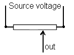
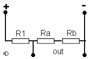
Syllabus Sections:- Potential dividers 2B1 8 Understand that two or more resistors can be arranged to act as a potential divider and apply the formula The formula is :- When a connection is taken from the junction between two resistors in series this is know as as fixed potentiometer or potential divider. Note that R1 is nearest to the Positive + rail and R2 is nearest to the Negative - rail. With the two resistors in this configuration a voltage somewhere between the maximum and minimum would be measured at the point marked "out" depending upon the values of the resistors. This fixed combination is usually replaced by a single resistor in which the output can be changed by moving a slider along the track.
The output could be taken from anywhere along the resistor. Without necessarily knowing it you have all used such a potentiometer on the audio gain control on your transceiver / receiver !!! Potential divider formula However a potential divider can be two or more resistors but what ever number it is the resultant formula would be Looking
at the diagram, you can see that the output is leaving the potential divider of R1, Ra and Rb at the link between R1 and Ra. With Ra
and Rb are in series we can simply add together their values
and come up with R2. This R2 we can use in the formula The Vout is thus dependent upon :-
Example if Volts in are 12V R1 = 10 ohms and R2 = 30 ohms then Vout= 12 x 30/(10 + 30) Vout = 12 x 0.75 Vout = 9V
|
|||||||||||||
|
|
|||||||||||||
|
|
|||||||||||||


 Potential
Divider


