|
|||||||||||||
|
|
|
||||||||||||
|
|
|||||||||||||
|
Syllabus Sections:- Reactive components 2D4 10 Understand the term 'self inductance' and recall that a 'back EMF' is produced as current flow changes in an inductor. In the Intermediate course you learned that :- A "conductor" is any piece of material that allows electrons to flow, such as a piece of wire, and that an "INDUCTOR" is normally a coil of a number of turns of wire. The wire is usually of large enough diameter so that it remains in the forms of the coil without collapsing if gently squeezed and is often in enamelled copper wire so that it is insulated from other components. Earlier in this course you learned that the abbreviation "emf" stands for electromotive force, which is measured in Volts and is the driving force or a pressure to propel electrons around an electrical circuit,
Self inductance Self Inductance is the property of an inductor which caused an emf to be generated in it as a result of a change in the current flowing through the circuit. If there is a steady current flowing in a coil then it produces a steady magnetic field surrounding the coil. When there is a changing current, the magnetic field also changes. The changing magnetic field causes an electromotive force (emf) to be induced in the conductor. The emf (voltage) is a self induced emf because it is induced in the conductor carrying the current and nothing else. So with a current change then there comes a change in magnetic field strength which produces the emf but in fact the emf produced opposes the change being made and is called a back emf. BACK EMF in an inductor Back emf is a emf produced in a conductor that tends to neutralize the applied voltage. The slow rise of current through a large inductor when a voltage is connected across it, is caused by the existence of a back EMF (electromotive force) which is a voltage generated by the magnetic field of the inductor working in opposition to the applied voltage. The back emf is particularly large when the rate of change (frequency) of current flow is rapid, (as occurs when a circuit is switched off). Lenz's Law says the induced emf always opposes the change producing it, which lead to the expression "back emf". If a back emf was not produced and instead the emf developed aided the inducing emf the induced current would create a bigger magnetic field which would produce more emf, producing more magnetic field, and so on to infinity, which would then lead to destruction of the component and probably worst!
Not in the 2021 Full Syllabus Recall that the inductance of a coil increases with increasing number of turns, increasing coil diameter and decreasing spacing between turns. From straight piece of wire to coil In the ILC you were introduced to the concept of inductance in relation to not only a single piece of straight wire but also when that wire was made into a coil the inductance increased, and that increasing number of turns, increasing coil diameter and putting the turns closer together the inductance increased. The inductance can be further increased by the use of a high permeability core. So
you should already have a working knowledge of this part
of the Advanced Syllabus
high permeability cores So what is a high permeability core? When you have an inductor wound on a former as part of a tuned circuit in order that the circuit can be "tuned" to a specific frequency the former is fitted with a high permeability core (also called a tuning slug). The core is threaded so that by the use of a non ferrous tool. When the core is wound into the coil the inductance is raised and when moved out the inductance lowers. This winding the core in or our of the former enables the tuned circuit to be brought to a point where it the coil and capacitor resonates. Sometimes the slug might be partially out of the core. This operation is called slug tuning. Coil with tuning slug
Should the inductance of the coil need to be further reduced this can be achieved by removal of the slug altogether or to achieve and even lower inductance can be achieved by the use of a "brass" slug The use of the core saves the need to change the size or number of turns on the coil.
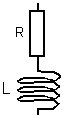
2D7 11 Understand the rise and fall of current in an LR circuit. Earlier you were exploring the RC in 3e.4 click here to check back and now we are going to look at an LR ( Inductor with Resistor ) circuit. A drawing
of an LR configuration of a series tuned circuit and here a
more complete With S1 open no current will be flowing the inductor L will have no resistance and for that moment have a resistance value of zero. The
effect of closing the switch allow current to flow in the
completed circuit through the resistor and there is an instantaneous change from no
current to finite current with a back EMF is developed by
the self inductance in the inductor L . Note: This back EMF is almost equal and opposite to the EMF supplied to the circuit. The back EMF is dependent upon a change in current and if the current does not change the back EMF stops. With no resistance from ohms' law V= I x R the resulting current would be infinite. There is an equation which indicates the time for the current IL ( the current through the Inductor )to reach 63% of the maximum I, (I2/R amps) after S1 is closed T(inductive) = L/R seconds This time for the current to reach 63% is called the LR Time Constant.
Not in the 2021 Full Syllabus Understand and apply the formulae for calculating the combined values of inductors in series and in parallel. The
formula is :- When inductors are linked in series or in parallel then the total equivalent value is similar in calculation to that of resistors. Thus total value of several inductors linked in series can be calculated from the formula:- Can you deduce the other formula for inductors in parallel ??
did you
works it out as
|
|||||||||||||
|
|
|||||||||||||


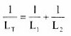 .................... just like
the resistor one !!!!
.................... just like
the resistor one !!!!