|
|||||||||||||
|
|
|
||||||||||||
|
|
|||||||||||||
| Syllabus Sections:- Transmitter concepts 3A2 19 Recall the meaning of Modulation Index and its effects on the number of FM sidebands The modulation index (or modulation depth) of a modulation scheme describes by how much the modulated variable of the carrier signal varies around its unmodulated level. Put it another way FM Modulation Index is defined as the ratio of Frequency Deviation to the Modulating Frequency FM modulation Index = Frequency Deviation / Modulating Frequency Note that the carrier Frequency is not mentioned and this means that the Modulation Index is totally independent of the carrier Frequency. The modulation of any carrier in any way produces sidebands. The FM sidebands are dependent on both the level of deviation and the frequency of the modulation. In fact the total spectrum for a frequency modulated signal consists of the carrier plus an infinite number of sidebands spreading out on either side of the carrier at integral multiples of the modulating frequency. As the level of the modulation index is increased the level of sidebands increases in level. |
|||||||||||||
|
3B1 19 Understand the block diagram of an s.s.b transmitter employing mixers to generate the final frequency. Note:
The diagram shows the Balanced Modulator and the Filter as
two separate items but sometimes they are combined into a
Balanced Modulator with Filter in one
block
. A general over view When considering a transmitter it is probably best to think what it is trying to do. So what is it trying to do ?
Understand the block diagram of an FM transmitter employing either frequency multipliers or mixers to generate the final frequency.
Fig. 2  Note A In the diagram the Microphone feed the Audio Amplifier which when feeding the Oscillator directly is feeding it with Frequency Modulation caused by the Microphone. Note
B In the diagram an alternative is
for the Audio Amplifier to feed Phase Modulation directly to
the Buffer Amplifier. Phase modulation works by modulating,
or changing the rate at which the audio sine wave
moves relative to an unmodulated wave. frequency multipliers This FM version is using frequency multipliers. The Audio signal is acting directly onto the frequency oscillator which then passes the signal to a buffer amplifier to make it suitable to go into the frequency multiplier stage. When is has been multiplied up sufficiently to the output frequency it is filtered and the driver prepares the correct level of signal for the RF amplifier, which is followed by filtering to present the signal to the aerial.
So what else is there to know ? This general over view, above, has shown you what happens to the signal from mic to aerial. The other sections, which follow below will give a more detailed account as to the activity of individual parts. |
|||||||||||||
| Oscillators 3C1 20 Recall the effect and importance of minimising drift. In Amateur Radio frequency drift is the unintended and generally arbitrary offset of an oscillator from its nominal… With somewhat older radios 1970's to the hybrids of the mid 80's seem to drift sightly or be off frequency slightly. The most important aspect of drift would be to drift outside the prescribed band edges and thus interfere with other spectrum users. When any piece of equipment, using an oscillator warms up, the frequency of oscillation changes. In the design stage of the equipment such variation will have been taken into account. Should the frequency change after the warm up period then the effect of the change in frequency is called "drift". You can
sometime hear this drift of signals on the HF bands when older
equipment is being used and to keep track of the frequency you
would need to re-tune using the RIT. Then if you were to work
the station your TX would go out on the original frequency and
you would be Receiving on different frequencies as controlled
by the RIT. Should you own old equipment then you must keep the amount of the "drift" to a minimum less than 3kHz else you could move in frequency out of the pass band of the station that is tuned to your signal. This drift would cause interference to other stations using nearby frequencies and could result in out of band transmissions - hence the reason to minimize drift. There could be calculations in relation to this question such as how much drift could be allowed to occur before reaching a band edge. Drift is considered in ppm which is Part Per Million. so at 145MHz a drift of 40 ppm would be 145 x 40 = 5800Hz or 5.8kHz so with the band edge at 146MHz you could only go upto 146,000,000 - 5,800 = 145.994MHz. Understanding
ppm and that MHz is a million Hz make the calculation quite
easy when you bring everything to Hz and then convert back to
MHz etc
|
|||||||||||||
| Crystal
oscillator
The start of this process is with the crystal oscillators. These have to create :-
frequency suitable for the part of the circuit in which they are employed. The reason for the stability is so that they do not "drift" off frequency and possibly put the transmissions outside the amateur bands but almost certainly a drift in frequency would take you into another QSO!! (Drift is a slight and gradual, yet unwanted change or frequency.) The reason for the accuracy is that you must know for absolute certainty that you are inside the amateur bands. It is desirable to ensure that you use the appropriate frequency for the mode you are using - SSB, FM, CW or data ETC. There are several ways to achieve the above:- Crystal oscillator The old way was to use a crystal oscillator and to change the crystal to change frequency, very stable and the frequencies are accurately known but limited to the number of crystals you have and they were and still are expensive! VARIABLE Frequency Oscillator Another old way was to use a VARIABLE Frequency Oscillator. This gave you an infinite number of frequencies in a section of the amateur band. Changing bands involved using a harmonic (multiple) of the same oscillator and retuning later stages of the transmitter to suit. The draw back was that such units were affected by heat, impact, when, say, you tapped your rig (microphonics) and thus did drift off frequency, and could give additional modulation to the wanted mode. Frequency synthesiser The modern way is to use a crystal oscillator which gives a stable frequency and link this to a frequency synthesiser which then gives you an accurate range of frequencies. In all the methods mentioned above a stable voltage is needed which is in addition to the voltage power source for the power amplifier -again this is to ensure stability. The synthesiser has two variants the PLL or Phase Locked Loop and the DDS or Direct Digital Synthesis (the DDS is not covered here as not part of the syllabus). HOWEVER there is one draw back in using a synthesiser rather than a crystal oscillator or VFO and that is what is called "noise level" - this is the back ground level of noise present in higher quantities than crystal or VFO oscillators. WHY 2 Crystal oscillators? These are in two different parts of the circuits and thus are performing quite separate operations (Note: some designs can use more than two crystal oscillators). So what happens from microphone to aerial ? The audio amplifier is linked to the modulator. Once the appropriate modulation has been applied, we now have a modulated signal which may be appropriately filtered but it is not on the correct frequency. This signal is then mixed with the output from the synthesiser to produce the desired output frequency, this then passes into the RF power amplifier and then is filtered again before it goes into the aerial. So the transmitter has achieved
|
|||||||||||||
|
|
|||||||||||||
|
|
|||||||||||||
|
|
|||||||||||||


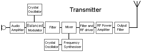 Fig. 1