|
|||||||||||||
|
|
|
||||||||||||
|
|
|||||||||||||
|
Syllabus Sections:- Microphone amplifier and modulators3E1 22 Understand the operation of a.m., s.s.b, and f.m. modulators. There
is a lt of what is believed to be "hidden" topics within
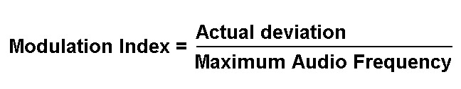
this section so let's first start with The meaning of the term peak deviation. When dealing with FM you will come across the term Peak Deviation which means the MAXIMUM amount by which the frequency of the signal may deviate from the carrier frequency. Deviation is the frequency change from the carrier frequency both above the carrier frequency and below. The amount of the deviation is proportional to the amplitude of the applied signal and NOT the frequency of the applied signal. Thus the louder you speak into the mic the greater the voltage that will be applied to the stage and the greater the deviation. Greater the applied voltage the greater the deviation Thus a signal of 3mV at 1kHz will create greater deviation than a signal of 1mV at 3kHz Now let us understand meaning of "Narrow Band" and "Wide Band" modulation for frequency modulation. The peak deviation is used to assess the Modulation Index. This is also know by the following :- Deviation Ratio = Actual Deviation / Maximum deviation In the world of broadcast radio the Modulation Index is 75kHz divided by 15kHz = 5 and being greater than one is described as Wide Band FM or WBFM. In amateur radio in the 2m band with 12.5kHz channel spacing the peak deviation is usually 2.5kHz with a maximum audio frequency of about 3kHz giving a Modulation Index of 0.83 and being 1 or less is termed Narrow Band FM or NBFM. Let's us explorer the meaning of depth of modulation for amplitude modulation. First let's recall the diagram of wave forms from your Foundation Licence course.
Thus the audio signal is carried as an exact image of itself on the AM signal, assuming no distortion which there must not be else the received audio would also be distorted. The Depth of Modulation It is typically the modulation index expressed as a percentage. Thus a modulation index of 0.5 would be expressed as a modulation depth of 50%, etc. Depth of modulation is the peaks and troughs of a modulated carrier wave Thus in the example shown M=A/B (0ther information sources may show this differently). It is said that the amplitude of the carrier wave is doubled because the variation between the peak and the trough of modulated is twice that of the carrier amplitude. Looking at value of A and B shows that the carrier wave is more or less 100% modulated, as half is amplitude above the carrier and half below .5 + .5 = 1 or 100% Increasing modulation further still would overmodulate the carrier causing break up in the signal and distortion in the resultant audio
Having got a
grip on the all of the above we can now take the
syllabus statement and look at it 3E1 22 Understand the operation of a.m., s.s.b, and f.m. modulators. Firstly
you must understand that the part of the Transmitter which is
doing the modulation in most cases is a MICROPHONE but of
curse we do have digital tones which in RTTY and FT8, as
examples modulate the audio. Let's recap what a transmitter does. The signal from a transmitter is know as the carrier wave whether it is AM FM of SSB - they are all the same. It is what is done to the carrier wave that make the difference mode, AM - SSB - FM. AM MODULATION The above is a diagram you have seen in the Intermediate Course. The modulation is achieved by varying the amplitude of the carrier, produced by the RF Oscillator, by the applied audio signal carried out in the modulator. The variation in the modulating signal or put it another way the frequency of the audio, is low by comparison to the carrier wave frequency.
All modulations using a change in amplitude of the output signal initially have four component parts:-
The side frequencies above and below the carrier are the "Side Bands" of frequencies or just side bands. SSB MODULATION In the SSB modulation whilst it starts off the same as the AM the transmitter then has to carry out two more functions:-
From the Intermediate Course comes again the diagram above and you learned that Modulator or Mixer uses the audio signal from the AF amplifier and the RF to produce four frequency components. But this is where the SSB transmitter differs from the AM transmitter. Note that in the SSB transmitter we are using a Balanced Modulator. This differs from the Modulator in the AM as only signals equal to the sum and difference of the RF and AF signals are output as sidebands. Neither of the original RF - the Carrier - nor AF signals are passed by the Balanced modulator also called a Balanced Mixer. Then as only one side band is wanted the other is filtered out prior to the signal passing into the power amplifier. FM MODULATION For the FM signal the modulation is different. Again the diagram is what you have seen in the Intermediate course but this time notice that the AF Amplifier is feeding its output to the RF oscillator and thus it is directly modifying the frequency of the signal and NOT the amplitude. 3E1 22 Calculate the bandwidth of such transmissions. a.m., s.s.b, and f.m. In communication systems we are not looking for the best possible reproduction of the original input into the microphone but a signal that gives good intelligibility of what was input into the microphone. This can be achieve with a signal about 2.5kHz wide. AM With a signal in of 2.5kHz the AM transmitter creates the side bands and it has been found by experimentation over the years of amateur radio that an AM signals need to have a bandwidth of about 5 to 6 kHz to achieve a good signal at the speaker of the receiver. SSB With SSB as one of the side bands is suppressed the bandwidth can be half that of the AM signal so a typical bandwidth is 2.5kHz FM In FM it is the frequency that is modulated by the input to the microphone The bandwidth needed for FM is similar to that of AM about 5 to 6 kHz . Carson's rule Defines the approximate modulation bandwidth required for a carrier signal that is frequency-modulated by a spectrum of frequencies rather than a single frequency. The
Carson bandwidth rule is expressed by the relation Bw = 2(Afmax+Δf
) Where Bw is the bandwidth requirement, Af is the highest modulating frequency Δf is the carrier peak deviation frequency For example, Carson's rule would say that the bandwidth of speech (300Hz to 3KHZ) with a peak deviation of 5KHZ would be. Bw = 2(3KHZ+5KHZ) Bw =2*8KHZ Bw =16KHZ
---------------------------------------------------------------------------
|
|||||||||||||
|
|
|||||||||||||