|
|||||||||||||||||||||||||
|
|||||||||||||||||||||||||
|
|
|||||||||||||||||||||||||
|
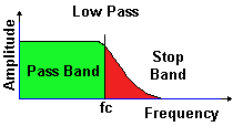
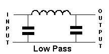
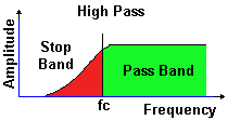
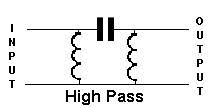
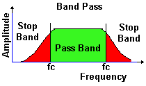
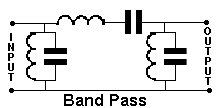
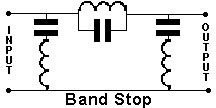
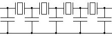
Syllabus Sections:- Filters 3E2 22 Identify typical sideband filter circuits and calculate relevant frequencies. The following are the diagrams of the filters as far as you have seen in the Intermediate course.
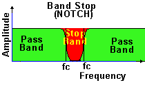
Whilst the input and outputs have been marked on some of the filters, with these simple filters the connection can be reversed but in complex filters this is not always the case. Let's look at the concept of the cut-off frequency. The cut off frequency of a filter is determined as the frequency where the amplitude of the signal is 3dB down from the maximum of the Pass Band, (ie half) that of the pass band or it can be said that the Fc is the frequency where the response is 3dB down.
Can crystals can
be used in filter circuits ? |
|||||||||||||||||||||||||
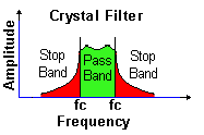
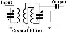
The crystal filter:Crystals can be used in filters and the diagram below gives an example of its use. Such filters are commonly used at intermediate frequencies above 500kHz. Note the use of the Xtal in the diagram and that the core of the transformer has dotted lines to indicate that it is a iron dust core Above is the diagram of another type of crystal filter The crystal filter uses a piece of quartz crystal exactly like a typical crystal used for stable frequency generation. The crystal is usually combined in a circuit with inductors and capacitors to give an impedance match between the stages of amplification that the filtering is applied to. In practice, because a single crystal is a very high "Q" device (and hence possesses a very narrow bandwidth), it is usual to build a crystal filter that incorporates several crystals. These crystals are all carefully chosen such that they are not all on the same frequency, but spread on, and around the centre frequency of the filter. In this way, a wider bandwidth for the filter may be obtained, whilst still maintaining the very steep "sides" of the filter characteristic. Unlike a conventional inductor/capacitor filter, where energy is stored magnetically in the inductor, and electrostatically in the capacitor, the crystal filter actually mechanically vibrates at the marked frequency. It works very much in the same way as a tuning fork, except that the frequency of operation is very much higher. As an example, if the filter is designed for 10.7 Mhz, then the crystal elements within the filter are actually vibrating mechanically at 10,700,000 times every second! ΔΔAn alternative to the crystal filter is the mechanical filter. These are not usually designed to operate much beyond 0.5Mhz, and their mode of operation is very similar indeed to the crystal filter. These filters possess an even sharper skirt, and where cost is not an issue, and design limitations allow, prove to be a superior choice. For budget applications, a ceramic filter is a low cost alternative. Performance of this type is not as good as the crystal filter, but it does allow a very useful filter to be constructed for the lower frequencies, whilst being suitable for miniaturization.
------------------------------------------------------------------------------------------ 3E2 continued and Calculate
relevant frequencies. For
calculations the formula from the formula sheet is bw = bandwidth AFmax = Maximum Audio Frequency Δf = peak deviation So
if you were given a peak deviation of 5kHz and maximum audio
frequency of 3.5kHz the band width (bw) would be bw
= 2( 5 +3.5) = 2( 8.5) = 17Khz |
|||||||||||||||||||||||||
|
|
|||||||||||||||||||||||||
|
|
|||||||||||||||||||||||||
|
|
|||||||||||||||||||||||||


 ..........
 which stand for :-