|
|
|||||||||||||
|
Bredhurst Receiving and Transmitting Society |
|
||||||||||||
|
|
|||||||||||||
|
3. Technical Basics 3g Tuned circuits 3g.1 Recall that a series or parallel circuit of a capacitor and inductor together forms a tuned circuit.
Tuned circuit is formed from a capacitor and inductor Inductors and capacitors can be used in circuits in two configurations to make :- Series tuned circuits and Parallel tuned circuit. Series tuned circuit
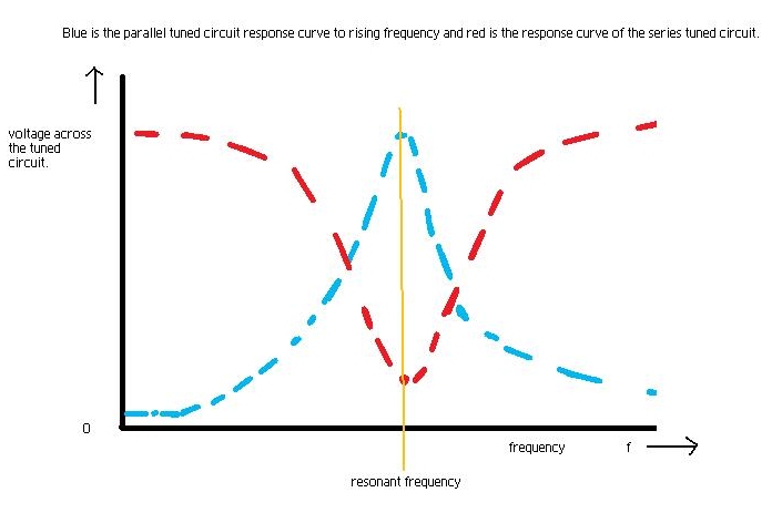
3g.2 Recall and understand that the energy stored in the capacitor and inductor can transfer from one to the other at a particular rate, known as the resonant frequency. Recall that the resonant frequency depends on the value of capacitance and inductance. Note that candidates must know that increasing L or C reduces the resonant frequency and vice-versa. Knowledge of the resonant frequency formula is not required. Earlier it was explained that a capacitor could store electric energy, and it stores it in the plates of the capacitor in the form of a charge. Also it was explained that an inductor can store energy in the form of a magnetic field generated by a previous flow of current. The diagram below shows a capacitor that can be switched across an inductor. If a charge were built up on the capacitor by another part of the circuit then when the switch is closed the potential difference due to the charge on the capacitor would cause electrons to flow through the inductor. As the current (electrons) flow from the capacitor it will slowly looses it charge, or as it is called "discharges", whilst at the same time a magnetic field builds up around the inductor. When the capacitor is fully discharged the current can no longer flow but then the magnetic field around the inductor starts to collapse and induces a potential difference, opposite to that was originally on the capacitor which causes a current to flow which recharges the capacitor. Thus once the magnetic field around the inductor has completely collapsed (reduced to nothing) the potential difference is zero - no current flows and the capacitor is then able to start to discharge again but this time in the other direction, until it is discharged at which point the inductor's magnetic field collapses again and the induced potential difference causes the current to flow to recharge the capacitor to the state it was when the switch was first closed. In theory the charge and discharge could continue forever (so long as the switch remains closed) but nothing is so perfect as there are losses in the circuit. Thus the charge and discharge will slowly diminish and eventually stop. The rate at which the charging and discharge cycle takes is determined by the value of capacitor its capacitance and the value of the inductor its inductance. The larger each of these values is the slower the charge and discharge cycle occurs. The frequency or rate at which the charge and discharge cycle take place is called the resonant frequency and then the tuned circuit is described as being resonant. Change the L or C and the resonant frequency will change. 3g.3 Recall that at their resonant frequencies, series tuned circuits present a low impedance, whereas parallel tuned circuits present a high impedance.
SO - Be aware that the circuits have many uses in radio frequency technology - in relation to AC / RF circuits as the principle does not apply to Direct Current as DC has no frequency of oscillation (it is constant all the time). |
|||||||||||||
|
|
|||||||||||||
|
|
|||||||||||||
|
|
|||||||||||||