
This page is an information and review of some parts you may already know from previous sections. We use this to help you get re- aquainted before proceeding to to main syllabus. The links to the syllabus sections are through the button at the bottom of the page.
Resonance
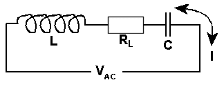
If we have a simple circuit of an inductor, capacitor and resistor linked in series and apply an AC voltage not only is there resistance due to the resistor but also due to the capacitor and the inductor.

Reactance is the oppositions to current flow in an AC circuit, so it can be thought of as AC resistance. This resistance however is caused by capacitors and inductors so to differentiate from "normal" resistance we call that caused by the capacitor Capacitance Reactance and that by an inductor Inductive Reactance.
Now with a LOW frequency being applied at ![]() the Capacitive Reactance will be
much larger than the resistance of
the Capacitive Reactance will be
much larger than the resistance of ![]() and the Inductive Reactance will be
much smaller when compared to both the Capacitive Reactance and
and the Inductive Reactance will be
much smaller when compared to both the Capacitive Reactance and
![]() .
.
When the frequency being applied at ![]() is made much higher, the Capacitive
Reactance will be much smaller than the resistance of
is made much higher, the Capacitive
Reactance will be much smaller than the resistance of ![]() and the Inductive Reactance
will be much larger.
and the Inductive Reactance
will be much larger.
| Frequency | Reactance | |
|---|---|---|
| Low | Capacitive HIGH | Inductive LOW |
| High | Inductive HIGH | Capacitive LOW |
It should therefore be apparent to you that at some frequency between these too extremes of low and high that the Capacitive Reactance and the Inductive Reactance will equal each other. Further because the voltage drop across the inductor and the capacitor are not only equal but 180o out of phase they cancel each other out.
At the point of Capacitive Reactance and the Inductive Reactance cancelling each other out, the only opposition to the current flow in the circuit will only be the resistor.
Let's have a look at what we have just said in graph form.
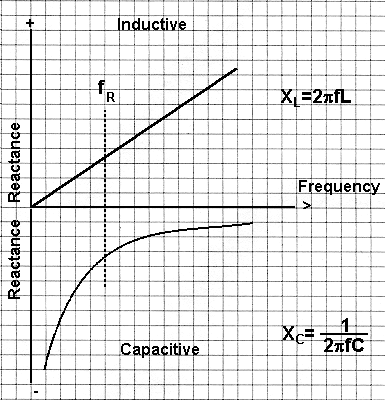
If we draw the graphs of Capacitive Reactance and the Inductive Reactance on a common frequency line we get :-

We mentioned above that at some frequency between these too extremes of low and high that the Capacitive Reactance and the Inductive Reactance will equal each other.
If you examine the graphs you will see that 5 units along the frequency axis and then 3 1/2 units along the resonance axis that the Inductive reactance at 3 1/5 is positive and the Capacitive reactance is 3 1/5 negative.
Only at this one particular frequency do the reactances have equal value BUT are opposite in sign and this is called
the Resonant Frequency
see the dotted line on the graph
Conclusion
We can now answer the question posed at the top of the page :-
What is Resonance and where can it be found ?
Resonance is that moment when the changing frequency of an oscillator reaches
a frequency when applied to a tuned circuit the Capacitive Reactance and the
Inductive Reactance are equal. It can be found easily from plotting a graph
as shown above at a frequency of ![]() and at no other point.
and at no other point.
Drinks break time !!!
I hope you are ok so far, as this is very heavy going relative to the Foundation and to the Intermediate Licence drink, or something, and then come back to it again refreshed, then press "To Tuned Circuits" button below for a little revision and on to the syllabus items.
The origin of some of the text on this page is from the RSGB with additions by the web master