
From the previous page you should now have an understanding of :
Resonance
Now to keep writing Capacitive Reactance and Inductive Reactance is rather long winded so we can adopt two symbols :-
Capacitive Reactance in an AC circuit is represented by ![]()
Inductive Reactance in an AC circuits represented by ![]()
In the formulae that follow they use certain symbols :-
![]() =
frequency in Hz
=
frequency in Hz ![]() = Inductance
in Henries
= Inductance
in Henries ![]() = Capacitance in Farads
= Capacitance in Farads ![]() 3.142
3.142
If we draw a graph of inductive reactance ![]() , against Frequency, we get :-
, against Frequency, we get :-

Note: Inductive reactance is considered to be positive.
If we draw a similar graph for capacitive reactance ![]() ,against frequency we get:-
,against frequency we get:-
Note: capacitive reactance is considered to be negative.
Syllabus Sections:-
2H1 Apply the formula for the resonant frequency of a tuned circuit to find values of f, L or C from given data.
At resonance XC = XL that means that the capacitive
and inductive impedance are equal we can use the following equation ![]()
Manipulating an equation can be quite daunting for some so this part will be further explained even more fully in the maths section.
| The |
||
| Now |
||
| so now divide both
sides by |
||
| thus | and now multiply
each side by |
|
| thus | this time take the square root of both sides | |
| thus | the equation at the top of this section. |
So now that you have seen how the equation has been derived from first principles what could it be used for ?
Well, if you wanted to know what value of a inductor is required to bring a system to resonance, whether that is an antenna or trap, the formula would be used if you know all but one of the factors in the equation. So you would need in this example to know the Frequency and the Capacitor's value. Knowing how to use a scientific calculator would also help and manipulation of formula.!!!
------------------------------
2H2 Recall the equivalent circuit of a crystal and that it exhibits series and parallel resonance.
The equivalent circuit of a crystal, which is a thin slice of quartz held in a holder, is shown immediately to the left. Points A and B are representing the crystal holder.
A crystal resonator (or crystal for short) consists of a piece of "quartz" set between two conducting plates. If a voltage is applied to the plates the resultant electric field causes stresses in the crystal to occur such that it vibrates at a certain frequency that is in built due to the size and cut of the quartz.
The equivalent circuit of a crystal with discrete components is a resistor inductor and capacitor in series and another capacitor in parallel as shown in the diagram with the point "A" and "B" each side of the parallel capacitor.
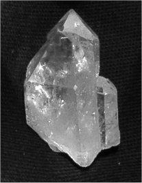
A piece of uncut Quartz crystal

Equivalent circuit to a crystal
2H2 Recall that crystals are manufactured for either series or parallel operation and will only be stable and correct on the marked frequency when used in the intended manner.
The crystal has two modes of resonance :-
Accept a frequency - or low impedance as a series tuned circuit used to pass a frequency in a receiver
Block at another frequency very close frequency or hi impedance or parallel tuned circuit used in an oscillator in a transmitter.
When obtaining crystals the frequency is quoted for 32pf capacity parallel resonance.
If that same crystal is used in the series resonance mode the frequency will be slightly different.
------------------------------
Know at resonance XC = XL and the formula for resonant frequency.
The formula is :- ![]()
You need to be familiar with the equation ![]() but where does it come from ??
but where does it come from ??
We know that at resonance in a tuned circuit the reactance of the capacitor is equal to the reactance of the inductor and the two equation associated with reactance are:-
| From | To find C this is what you have to do multiply both sides
by |
|
| giving | then divide both sides by |
|
| giving | now we need to "square" both sides to remove the "square root on the left hand side | |
| giving | which also equals |
|
|
|
||
| From | to find L divide both sides by C | |
| giving |  |
which we can also look at as |
Identify resonance curves for series and parallel tuned circuits
For this part of the syllabus all you need to remember is the shape of the resonance curves for series and parallel tuned circuits.
A series tuned circuit has its lowest impedance at resonance
A parallel tuned circuit has its highest impedance at resonance hence the term rejecter circuit. This high impedance at resonance is used for instance for "traps" in aerials to electrically shorten a dipole aerial making it operational in two bands - see section on antenna and feeders for more information.
The origin of some of the text on this page is from the RSGB with additions by the web master