
2E3 Recall that current lags potential difference by 90° in an inductor and that current leads by 90° in a capacitor.
Re-writing the syllabus makes it easier to understand
Recall that potential difference leads current by 90°in an inductor and that current leads potential difference by 90° in a capacitor.
However the voltage across the capacitor will lag the current by 900 and the voltage can be determined by V = I x Xc
So you cannot just add the voltages but they have to be added using a vector diagram.
Vector diagram
As we are in a series circuit the current is common for the resistor and to the capacitor and is the reference vector. However as we are discussing phases then let's call that the Current phase.
As the voltage is in phase with the current it can be drawn along the same line as the current and its length according to the voltage in this case 15V
The voltage through the capacitor is out of phase by 900 so we can draw that downwards and again is the length corresponding to it value in this case 12V.
The supply voltage is thus the sum of the vectors which equals the length of the diagonal line which can be worked out by the use of Pythagoras's Theorem equation
"the square of the hypotenuse = the sum of the squares on the other two sides"
Thus V2 = VR2 + VC2 where V = VT
![]()
Memory aid: This section is quite difficult to grasp for some students so an old hand at Amateur Radio, at a recent BRATS club meeting, suggested the following was added to the course notes.
with a Capacitor the current leads the voltage the so I leads the V thus this gives us Capacitor C IV
and with an Inductor voltage leads the current so V leads the I thus this gives VI L (Inductor).
With that in mind continue with the topic.
Capacitor - Current leads Potential Difference (C I V )
If the black curve now represents the current through a capacitor then the blue curve represents the potential difference across a capacitor. The current leads the potential difference by 900.
This capacitive reactance can be calculated by the
formula XC= 1/2 fC
fC
Units are:- f is in Hertz with C in Farads
Inductor - Potential difference leads the Current ( V I L )
If the black curve represents the potential difference across an inductor then the blue curve represents the current across an inductor. The potential difference leads the current by 900.
So let us explain further. When the Black curve is at position 0 the blue curve has not yet reached the same 0 position thus the black curve is said to lead the blue curve.
This inductive reactance can be calculated by the formula
XL=2fL
Units are:- f is in Hertz with L in Henrys
PD (Voltage Wave forms)
Taking this further at the point of supply of AC the wave forms of PD potential difference (voltage) and Current are in phase but when it encounters a capacitor then from above the current leads the PD (voltage) CIV thus in fact across the capacitor the PD or voltage wave will lag behind the supply waveform.
Had it been an Inductor then the PD (voltage) leads the current VIL thus in fact across the Inductor the PD or voltage wave will lead the supply waveform.
Can you draw the appropriate wave forms ??
The term 'reactance' describes the opposition to current flow in a purely inductive or capacitive circuit where the phase difference between V and I is 90°.
2E3 Understand the formulae for
the reactance of a capacitor or inductor in terms of frequency
and component value.
Calculate the unknown term given the other two.
The equations are :-
![]()
![]()
Reactance
Reactance is the opposition to current flow in an AC circuit and can be loosely thought of as AC resistance and has values in ohms. This "AC resistance" is not actually resistance and it must be remembered that a capacitor stores energy electrostatically and an inductor stores energy magnetically.
Taking the case of the capacitor it can be loosely thought of as a very small rechargeable battery which accepts a charge and can then accept no more. On the next half cycle the capacitor then gives up that charge back to the supply and charges in the opposite direction. For this reason a "perfect capacitor" (one with no losses) does not get hot. It will be appreciated that the capacitor will charge and once charged can pass no more electricity hence it then apparently acts as an open circuit.
To differentiate from "normal" resistance we call that caused by the capacitor Capacitance Reactance and that by an inductor Inductive Reactance and both have values in ohms.
![]() ,
in ohms, represents capacitive reactance in an AC circuit.
,
in ohms, represents capacitive reactance in an AC circuit.
![]() ,
in ohms, represents inductive reactance in an AC circuit.
,
in ohms, represents inductive reactance in an AC circuit.
In the formulae that follow they use certain symbols :-
![]() =
frequency in Hz
=
frequency in Hz ![]() = inductance in henries
= inductance in henries ![]() = capacitance in Farads
= capacitance in Farads
![]() = 3.142
= 3.142
If we draw a graph of inductive reactance ![]() , against Frequency, we get :-
, against Frequency, we get :-

Note: Inductive reactance is considered to be positive.
If we draw a similar graph for capacitive reactance
![]() ,
against frequency we get:-
,
against frequency we get:-
Note: capacitive reactance is considered to be negative.
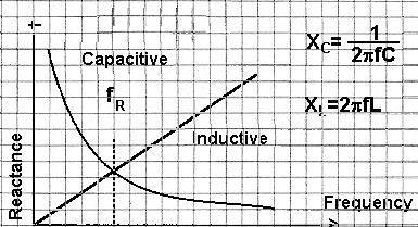
Now, if we have an LC circuit and draw both graphs on a common frequency line we get :-
Examination will show that only at one particular frequency the reactances are equal and opposite → FR the resonance frequency (see the dotted line).
This diagram may make it a little easier to see that the XC = XL and thus cancel each other out as the XL is the positive and XC a negative
We have spoken about the reactance of the coil (inductor) which is
like resistance but the coil still has "normal" resistance and
for these calculations we call this ![]() and identify it in
the circuit diagram as a resistor.
and identify it in
the circuit diagram as a resistor.
Let ![]() =
= ![]() = 10k and
= 10k and ![]() = 10R
= 10R
![]() 10mV
RMS at the resonant frequency.
10mV
RMS at the resonant frequency.
as ![]() and
and
![]() cancel each other out, so
cancel each other out, so ![]() =
= ![]()
Thus ![]() =
= ![]()
Thus ![]() =
= ![]() = 1 mA
= 1 mA
Voltage across ![]() or
or ![]() x
x ![]() or
or ![]() /p>
/p>
Thus Voltage across ![]() or
or ![]() =
= ![]()
Thus Voltage across ![]() or
or ![]() = 10 volts
= 10 volts
The "gain" between the input and the output is known as magnification factor which in this case = 1000 (10mV rising to 10V = 1000 times) and thus the
magnification factor at resonance = ![]()
By varying the frequency of the input current, the
point where ![]() =
= ![]() approaches and a circulating
current
approaches and a circulating
current ![]() increases to a maximum in the parallel loop
limited only by
increases to a maximum in the parallel loop
limited only by ![]() . The voltage across the circuit
. The voltage across the circuit
![]() =
= ![]() x
x ![]() .
.
At the same time the overall resistance to the input current rises to a maximum and the through current is a minimum.
Assuming that we loosely couple a signal generator into the inductor of a parallel LC circuit and measure the voltage across with an RF voltmeter
Now let us sweep the input frequency and draw graph of the resulting voltage changes.
![]() is the resonant frequency giving a peak voltage,
is the resonant frequency giving a peak voltage,
![]() .
.
The points either side are generally accepted as limits of usable
frequency - This range ![]() to
to ![]() is the bandwidth [eg. 12kHz
for speech] for a parallel LC circuit, which could be the load
in a power valve RF amplifier.
is the bandwidth [eg. 12kHz
for speech] for a parallel LC circuit, which could be the load
in a power valve RF amplifier.
Q Meter
This measurement, requiring only a voltmeter, is used in a common form of Q meter. Q meters give a measure of "Goodness" of a component or circuit.
In this case ![]() =
= ![]()
i.e. the Bandwidth compared to the resonant frequency = SELECTIVITY
In the exam the sheet of equations shows this formula as
fC = centre frequency fU = the upper frequency and, fL = the lower frequency
There is also something called Carson's rule which is related to the above.
This defines the approximate modulation bandwidth required for a carrier signal that is frequency-modulated by a spectrum of frequencies rather than a single frequency.
The Carson bandwidth rule is expressed by the relation Bw = 2(Af+Δf )
Where Bw is the bandwidth requirement,
Af is the highest modulating frequency
Δf is the carrier peak deviation frequency
For example, Carson's rule would say that the bandwidth or speech (300Hz to 3kHz) with a peak deviation of 5kHz would be.
Bw = 2(3kHz+5kHz)
Bw = 2*8kHz
Bw =16kHz
If we build a receiver for say 120kHz, the RF stage (if we still require 12kHz speech bandwidth) will have a measured "MAX"
![]() =
=
![]() =
= ![]()
![]() =
= ![]()
NOTE: an ![]() of
of![]() is very low !!
is very low !!
![]() (Quality Factor)
(Quality Factor)
Providing ![]() is greater than a single figure the following
basic statements are true with small and negligible errors.
is greater than a single figure the following
basic statements are true with small and negligible errors.
![]() =
= ![]() , the MAGNIFICATION FACTOR is
, the MAGNIFICATION FACTOR is
![]() =
=
![]()
The parallel resistance of a tuned circuit at resonance is ![]() x
x ![]() . This is known as the DYNAMIC
resistance
. This is known as the DYNAMIC
resistance
An example of this is shown, a parallel tuned circuit in the "ANODE" of a RF amplifier.
Let ![]() = 1000 Ohms
= 1000 Ohms
and ![]() = 100
= 100
To tune to resonance we adjust ![]() until the
DYNAMIC RESISTANCE is HIGHEST, ie for a max dip
on the ammeter.
until the
DYNAMIC RESISTANCE is HIGHEST, ie for a max dip
on the ammeter.
The coupling resistance to the next stage (Dynamic Resistance) is
![]() x
x ![]() = 100,000 Ohms
= 100,000 Ohms
The series RF resistance of the coil
= ![]() = 10 Ohms
= 10 Ohms
The general expression for Dynamic Resistance is :-
![]() =
= ![]() which does not include any frequency component.
which does not include any frequency component.
It is obvious from this that the larger ![]() compared to
compared to ![]() ,
the higher will be the Dynamic Resistance and
,
the higher will be the Dynamic Resistance and ![]() .
.
2E4 12 Understand the use of capacitors for AC coupling (DC blocking) and decoupling AC signals (including RF bypass) to ground.
It should be clear to you that from the construction of a capacitor (two separate plates with no link between them) provided no path for DC to pass. Thus it can be said that capacitors block DC and thus can be used for blocking DC in a circuit.
On the other hand in an AC circuit current appears to pass because of the build up and decay of the charge on one plate and then the other AC changes direction of its flow of electrons.
If therefore there is the possibility of an AC signal (and this includes RF which is also AC) in a DC circuit then this can be channelled to ground via a capacitor and as such this is called decoupling hence the term "decoupling capacitor".
Take a look at this:
![]()
C1 and C2 are acting as DC blocking capacitors but allow rf signals through. C3 is acting as a "decoupling capacitor" as the circuit is amplifying AC signals but any that might flow from the emitter of the transistor will be taken to ground via the Capacitor C3, but any DC signal will not be passed instead it will travel to ground through R4.
2E5 Understand the use of inductors for DC decoupling (AC blocking)
An inductor is a passive electronic component which is capable of storing electrical energy in the form of magnetic energy. Basically, it uses a conductor that is wound into a coil, and when electricity flows into the coil it will generate a magnetic field.
If we assume that an AC current is flowing through the inductor. When current is about to flow to the inductor, the magnetic field generated by that current cuts across the other windings, giving rise to an induced voltage and thus preventing any changes in the current level.
These effects of the induced voltage are produced even when the direction in which the current is flowing is reversed. Before overcoming the induced voltage that is attempting to block the current, the direction of the current is reversed so that there is no flow of current.
The current level remains unchanged when DC (direct current) flows through the inductor so no induced voltage is produced, and it is possible to consider that a shorted state results. In other words, the inductor is a component that allows DC, but not AC, to flow through it.
A power supply is not necessarily clean enough so as not to affect circuits. Decoupling works both ways and a ferrite bead can be utilised intending to keep noise on a power supply from affecting the circuits - which can be clocks or high speed integrated circuits(I.C.), and block I.C. noise from getting through to the supply rails which can affect other parts of the circuitry. This is true in the case of Switch-Mode Power supplies where a wire through a ferrite bead can be an inductor that blocks power supply noise and vice versa with circuit noise blocked from the power supply. In extreme cases a true coil inductor is used allowing D.C. to get through to components and blocking any A.C. ripple or noise, and even RF in the collector circuit of a transistor getting back to the P/S.
The origin of some of the text on this page is from the RSGB with additions by the web master