EMC ( Electro-Magnetic Compatibility )
Routes of Entry
6C1 Recall that direct pick-up in affected devices tends to be independent of the transmitted frequency within a band although differences may be noticed between different bands.
When we are dealing with direct pickup we are not dealing with an interference that has passed though any tuned circuits but interference that is having a direct effect on components within the piece of electronic equipment.
The direct (internal) pickup and conducted pickup is by loudspeaker leads and occurs over a wide range of frequencies. So tuning a radio receiver from one end of the band to the other and listening for a received signal has minimal usefulness. The action of the tuning is merely a diagnostic tool. If there is no adverse signal detected whilst tuning then the most likely culprit is direct pickup, in other words you are eliminating other RF causes via cables etc.
Recall that direct pickup is especially an issue in the VHF/UHF bands.
The VHF and UHF frequencies can more easily excite cables and components in domestic receivers and so are more likely to give rise to interference in them. This is the main cause of direct pickup for domestic radios and TV.
6C2 Understand that some masthead and down-lead TV amplifiers are broadband, amplifying a wide range of frequencies, including amateur frequencies.
Understand that this can result in overloading of the amplifier and/or the TV input.
One of the biggest problems to overcome, should you or more especially your neighbour suffer from interference from your transmitter, will be if there is a mast head amplifier on the TV / radio antenna.
There will be many occasions where the amplifier is just not needed but may have been installed as a "fad". The problem you face as an amateur is that the amplifier to do its job property has to be very broadband and in being broadband amplifies a great many signals including amateur radio signals. The effect of this is that the TV's input stage is overloaded which causes distortion or cross modulation as it is called (but you do not need to remember that word "cross modulation" for the exam just remember distortion !!!)
If a mast head amplifier really is needed then a filter at the TV antenna input will help the situation as will a "band specific" mast head amplifier.
Filtering and remedial measures
6D1 Understand that filters can be fitted in the leads from the power supply to the transmitter to help minimise RF energy entering the mains wiring.
Recall the use of ferrite ring filters for minimising unwanted RF on antenna down-leads and mains leads to affected equipment.
Use ferrite rings on 12v leads and mains leads
It is important to understand that the power lead from the mains socket from the rig or from power supply is susceptible to allowing RF entering the cable, and for this to be transferred to the mains power in your property.
Proper filters must be used with consideration given to safety when using mains power. Consideration could be given to using ferrite rings at both ends to the mains lead - near the socket to stop RF entering the property supply and near the Rig or power supply to stop it entering the that equipment. The filter acts as an RF choke thereby stopping RF.
Items connected to the transceiver
Any items that you have connected to the transceiver such as a computer and TNC can also give rise to EMC problems and thus all interconnecting lead need the Ferrite ring treatment !!!
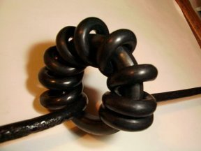
It is hoped that you recall this picture form the FLC course. Whilst the cable wrapped onto the ferrite ring in this case is RF feeder it could just as easily be the 12v lead - the mains lead - the sound card leads etc.
In any question asked on this part of the syllabus the answer will lie in stopping the RF going where it should not and generally the answer will be "by the use of a filter" or by the use of a ferrite ring !!!
One of the most useful assets that the radio amateur can own are ferrite rings. In value for money terms they are wonderful. The ferrite ring is effective for RF signals on mains and audio leads and for RF signals picked up by the screen of coaxial cables and down leads. However if the signal is picked up by the antenna and conveyed to the device via the inner conductor then the ferrite ring is ineffective and a filter tuned to the appropriate frequency is required.
Understand the use of mains filters to reduce RF, electric motor and thermostat interference to TV, radio and audio systems.
In-line mains suppression filters are effective for interference conducted along the mains wires however if the source of the problem is know it is better that the item is repaired or replaced, but at least try filters first before throwing away a piece of equipment.
Please note that spike filters sold for computers often do not have any RF suppression just a VDR (voltage dependent resistor) for spike suppression.
Recall and understand the use of high-pass or low-pass filters to reduce the level of HF and VHF amateur transmissions into other electronic equipment.
As we learned earlier, for HF we need to use a low pass filter to prevent HF harmonics from radiating. If your VHF/UHF signal is causing a similar issue then a VHF or UHF low pass filter can help prevent it.
6D2 Understand the meanings of common mode and differential mode currents and signals.
In the antennas and feeders section we saw that at the feed point of an antenna with co-ax cable, there is a balance between the inner and outer currents inside the cable. These should be equal and opposite to cancel each other and are called differential mode currents. However, if the antenna is not perfectly tuned for the frequency being operated then there will be some over-spill of current down the outside of the co-ax braid. This is called common mode current. It is this current that can radiate out to cause interference.
Understand how a ferrite ring or choke can be used to attenuate common mode signals in twin wires and braid currents on coaxial cables.
We saw earlier that a ferrite with several turns of co-ax cable is called a current balun which prevents these common mode currents from radiating. With twin feeders the two wires in the feeder cable will have differential mode currents that counterbalance each other, but being open wires some common mode current will radiate signals at the sides. Help to eliminate these common mode currents can be made by passing both wires through one or more ferrite rings at the transceiver end of the feeder.
6D3 Recall how to use a suitable general coverage receiver to check for spurious and harmonic emissions from the station.
General coverage receiver is also a piece of test equipment
![]() Students
sometimes forget that a general coverage receiver is not only used
for listening to stations but is a valuable piece of
test equipment for checking for harmonics.
Students
sometimes forget that a general coverage receiver is not only used
for listening to stations but is a valuable piece of
test equipment for checking for harmonics.
Your amateur radio station is not complete without a general coverage receiver. Few will however consider it as a piece of test gear but as far as EMC is concerned that is exactly what it is.
The general coverage receiver can be used it to check out your station for spurious RF emissions and RF harmonics by, whilst transmitting a very low power, tune the radio receiver from below your transmit frequency up the range of the receiver. Remember to calculate the harmonic frequency to particularly check these frequencies as you tune through the frequencies.
If you find an oddity then you can stop the transmission and if the oddity stops you know that your transmission was causing a problem if it does not stop then it is not your transmission at fault.
Of course there is a limit to the frequency range of general coverage receivers so they are limited in their testing ability.
However if you were looking for harmonics of 1.96MHZ then on a general coverage receiver of 0 to 30MHz you would be able to check up to the 15 harmonic 1.96 x 15 = 29.25MHz !!!!
You will want to check all the modes you use, as FM gives you least problems with EMC then comes CW and worst of all is SSB.
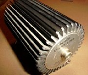
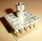
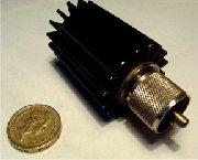
6D4 Understand the use of a dummy
load in fault finding.
Recall that the resistor(s) used in a dummy load must be
non-reactive and of a suitable power rating.
Recall how to use a dummy load to check if interference is
being caused by a radiated signal or leakage into the
mains or other wiring.
Elsewhere in the course discussion has taken place about the DUMMY LOAD and that it is important for an amateur radio station to have one. The dummy load is a very good piece of test equipment as it is used in place to the radiating antenna and so long as it is of sufficient power handling capability will remove the RF field whilst you are trying to establish if you are causing the RF problems. <>
It the problem does not disappears when the dummy load is used then the problem is likely to be that the transmitter is sending RF down through its power supply into the mains lead and thence into the mains supply. If the problem can be solved by fitting ferrite rings to the mains lead of the transmitter and then when removed the problem returns, then the transmitter is almost certainly sending RF into the mains.
If when the antenna is used the interference returns then put the ferrite ring on the mains lead to the affected device as the mains lead of the device may be acting as an antenna!!
We discussed earlier that dummy loads should ideally be made from one or more carbon resistors, as other types have an inductive effect, and ideally shielded to the outside world by a metal enclosure. Transmitting a carrier into a dummy load will cause it to heat up quite a lot as all the RF energy is converted into heat. We must make sure that the we do not exceed the power rating of the dummy load.