

Technical Basics
Types of antenna
4D1 Recall that a three-element Yagi has a half-wave driven element, a reflector that is slightly longer than the driven element and a director that is slightly shorter than the driven element.
Recall that Yagi antennas may have more than one director.
Yagis can be made to have a sharper width of radiation by adding extra elements on the front and these are directors, from 1 director giving a wide beam width to many directors making a sharper beam width. More directors give more antenna gain.
4D2 Recall that an antenna trap is a parallel tuned circuit and understand how it enables a single antenna to be resonant and have an acceptable feed-point impedance on more than one frequency.
Here we have a "trapped dipole" diagram showing the tuned circuits which in the antenna construction are called "traps". They are a simple tuned circuit that by their placing in the dipole elements give a second frequency band so now there are two bands we can use from a single feeder. The traps in each leg of the antenna should tune the same frequency. First we build the dipole on the highest frequency band we want to operate, then when all is well we add the traps and extra wire which is then cut to give a half wave dipole on the second band which is at a lower frequency. Normally these two bands are not too far apart in frequency. The overall effect gives us a shorter length of dipole resonance on the lower frequency band than if we had just made a single dipole for that lower band.
Recall that this technique may be extended to multi-element antennas such as Yagis.
This effect of adding traps can be used on yagis too! And for more than 2 bands. See our club's 4 element trapped HF antenna for 3 bands on our front page click here. In the photo you can just make out the traps in the yagi elements.(of course the traps are weather proofed so rain cannot spoil their components inside the traps).
Standing waves
4E1 Understand that the signal reflected back
down the feeder will combine with the waves travelling up the
feeder from the transmitter leading to the formation of
standing waves.
Recall that both forward and reflected signals are subjected
to feeder loss.
A concept difficult to grasp is that the signal that is sent back down the feeder due to a mismatch is not lost but will combine with the waves travelling up the feeder from the transmitter.
Standing waves are produced whenever two waves of identical frequency interfere with one another while travelling opposite directions along the same feeder.
The amplitude of the wave going forwards is added to the amplitude of the wave going backwards in accordance with the principle of superposition which means that sometimes the waves create a larger wave because they are in phase and sometimes null out completely when they are in anti phase.
These new peaks and troughs are the "Standing Waves" and are characterized by certain fixed points along the feeder which undergo no displacement.
However the standing waves affect the impedance "seen" by the transmitter and if the impedance mismatch to 50 ohms is too great, a modern rig will shut down due to the in built protection. However older equipment may well be damaged due to incorrect impedance.
The correct idea here is to ensure that you check the impedance mismatch with your SWR (standing wave meter) on low power.
Recall that the reflected signal will change the input
impedance of the feeder so that it is no longer the
characteristic impedance and the feeder will not then present
the correct impedance to the transmitter.
The Characteristic impedance of a feeder for coax in nominally 50 ohms. An antenna will only present an impedance near to 50 ohms when the antenna is the correct size for the applied frequency. It is only at this time will the antenna and the feeder ensure maximum transfer of power. Any mismatch will result in some power being reflected back down the feeder.
The mismatch which has the result of forming the reflected signal and thus the Standing Waves then presents to the transmitter's antenna socket and altered impedance rather than the characteristic impedance which the transmitter was expecting.
Antenna matching units
4F1 Recall that a transmitter is designed to
transfer energy into a specific impedance.
Understand that an Antenna Matching Unit ( AMU ) can change the
impedance presented to the transmitter and that an
AMU does not tune the feeder or the antenna to resonance.
Understand that if the AMU is located at the transmitter, it will have no effect on the actual SWR on the feeder between the AMU and antenna. It is often mis-named as an ATU.
So if you have made a dipole antenna cut to what you calculate is the correct size of the frequency you wish to operate but then find you have a Standing Wave Ratio or SWR greater than say 1.5:1 you would need an AMU ( Antenna Matching Unit ) to match the antenna to the rig
NOT TUNE THE ANTENNA
An AMU matches, it does not tune !!
There is a conflict of words when discussing ATU (antenna tuner unit) and antennas. An antenna can only be "tuned" by cutting it to the correct length. Thus the term ATU should really be an AMU or Antenna Matching Unit. By adjusting the AMU it alters the impedance seen by the transmitter to as near 50 ohms impedance as possible . The AMU is then said to "tune out" the mismatch, or put it another way, tune out the standing waves on the feeder - BUT it is NOT TUNING the ANTENNA.
Resistive Load
Further the main use of the AMU is to present a resistive load rather than an inductive load, at the correct impedance, to the transmitter.
Change frequency or band, then a re-tune of the AMU is required
The tuning out of the mismatch must be carried out for possibly any frequency change but most especially when there is a band change. The reason for this is that there will be a charge in the impedance of the antenna with a change of frequency.
Have your tutor demonstrate such a "tuning" up at your club nights - the BRATS can help at any club meeting during the year.
![]() For
the Intermediate Exam you do not have to be aware as to how
the matching takes place just that it is possible and that an
AMU MATCHES the antennas impedance to the rig and DOES
NOT TUNE the antenna.
For
the Intermediate Exam you do not have to be aware as to how
the matching takes place just that it is possible and that an
AMU MATCHES the antennas impedance to the rig and DOES
NOT TUNE the antenna.
A transmitter is designed to "see" a specific impedance at its aerial socket. If it does not "see" this impedance then the PA (Power amplifier) cannot operate efficiently.
Plugs and sockets
4G1 Recall that in a correctly connected
and terminated coaxial cable the RF field only exists within
the cable and is not affected by objects
outside the cable.
Note that correctly connected means screen and inner conductor
continuity through any plug and socket.
We saw in the Foundation Course some types of plugs, and some shown connected to co-ax cable. It is important that you use a 50 ohm plug with a 50 ohm cable for connection integrity of the 50 ohms. This is so the RF travelling down the inner wire is perfectly shielded by the co-ax outer shield and does not escape by badly fastened connectors ensuring the RF stays within the cable. The plugs used and the sockets they plug into maintain this continuity of shielding from co-ax cable right through to your radio equipment.
Not in this section of the syllabus, but you should know that a dummy load is a useful device to help test your transmitter.
The dummy load is a substitute for an aerial and as such is also called an artificial antenna and as far as transmitters or receivers are concerned it electrically resembles an aerial (usually 50 ohms impedance) and thus can stand totally in place of an aerial. The dummy load is a piece of test equipment which all radio amateurs should own.
The dummy load enables a transmitter to be tested without radiating a signal (or at worst a very low radiated signal). When connected to a receiver it does not pick up external RF signals and RF noise.
When testing a transmitter the Dummy Load must be capable of safely dissipating , as heat, the output power of the transmitter.
Carbon Resistor NOT wire wound resistor
The dummy load is a large resistor of usually 50 ohms (or a number of resistors to make up the required wattage dissipation). The resistor is set inside a suitable screening enclosure and has a connector so that it may be linked by a coaxial feeder to the transmitter or receiver or even the end of a coaxial cable run which is under test.
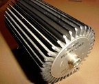
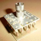
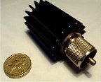
Above are three examples of dummy loads
The origin of some of the text on this page is from the RSGB with additions by the web master