

Radio Propagation:
Key Concepts
5A2 Understand the meaning of ground wave, tropospheric (space) wave, sky wave, skip distance and skip zone (dead zone).
We learned earlier in "Antennas and Feeders" section and in the Foundation course that radio waves travel in straight lines.
There are certain terms associated with propagation that are now introduced :-
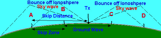
GROUND WAVE = the radio waves that hug the earth but quickly become weaker with a ranges of a few kms at best.
SKY WAVE = the radio waves that are reflected back to earth by the ionosphere. Even very low powered HF transmitters are capable of having their signals reflected back from the ionosphere as it is not the power of the transmitter that is needed to make the signal reach the ionosphere, the power is only needed to be sufficient for the signal to be heard by the receiving station. QRP operation on less than 5 watts has reached Australia!
SKIP DISTANCE = the distance from the transmitter to the first point at which returning sky wave is received back on earth having been reflected by the ionosphere.
SKIP ZONE = The zone is between the end of Ground Wave coverage and the point at which returning sky wave is first received back on earth. Thus the SKIP ZONE (also called the Dead Zone) is signal free as far as communication is concerned as nothing is heard from the transmitting station.
All the distances change as the ionosphere changes so you cannot state the the Skip Zone is such and such a distance and the same goes for the Skip Distance.
Skip distance minus ground wave distance = the skip zone distance
Note:- NO SIGNALS are received in the SKIP ZONE from the transmitting station's antenna location!!!
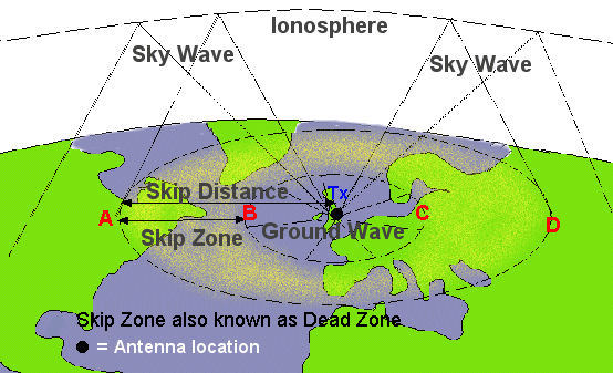
The Tx indicates where the Transmitting station is located. Stations at A, B, C, and D will hear the signals but for different reasons.
Ground Wave
Stations B and C are near enough to hear the grounds wave signal
Sky wave
Stations A and D are far enough away (outside the Skip Zone or DEAD ZONE) to hear the signals from a bounce off the ionosphere.
Skip Zone also known as DEAD ZONE
The Skip Zone or DEAD ZONE is as it says no signals will be hear from the transmitting station. so anywhere between A and B and C and D will not hear the transmissions.
5A3 Recall that the ground wave has a limited range due to absorption of energy in the ground and that the loss increases with increasing frequency.
The ground wave only goes a few kilometres before reflections from trees and buildings but mainly absorption by the ground make it diminish in strength. The effect is noticed less at lower frequencies but happens more at VHF frequencies.
5A4 Recall that electromagnetic radiation
comprises both an electrical field and a magnetic field.
Recall that the two fields are always at right angles to
each other and that the direction of propagation is at
right angles to both fields.
It is the electrical field which determines or defines what is called the polarisation of the radiation wave.
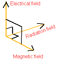
At HF the polarisation of a wire antenna does not matter too much because of the irregular scatter pattern created by twisting in the ionosphere. Polarisation does matter at VHF frequencies. An RF signal is an electromagnetic signal which has an Electric Field (E) at right angles to the direction in which the wave is travelling and a Magnetic Field component (H) which is at right angles to both the Electric Field and the direction of wave travel. The three components are in 3 different planes. Try to understand the diagram.
When using VHF and UHF the best signals will normally be received if the same polarisation is used for the transmitter and receiver - else significant attenuation occurs.
Recall that it is the plane of polarisation of the electric field that defines the polarisation of the electromagnetic wave.
Note the Electric Field as in the diagram. The "E" field is at right angles to the magnetic field and also the field of radiation.
Ionosphere
5B1 Understand that the ionosphere comprises layers of ionised gases and that the ionisation is caused by solar emissions including ultra-violet radiation and charged solar particles.
Recall the ionospheric layers (D, E, F1 and F2) and approximate heights.
You should be aware that HF propagation is predominantly due to ionisation of the ionosphere and that the ionosphere is made up of layers of gases.
We must now consider what these layers of gasses are called. These layers are simply called the D E and F layers there are no A B C layers.
| Layer | Approx Height |
|---|---|
| F | 400 kms |
| E | Varies |
| D | 70 kms |
Troposphere is below the D Layer
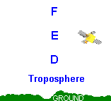
Above the troposphere the D layer is nearest to the earth at about 70kms and the top layer, the F layer is at about 400kms. The E layer sits between the D and the F layers.
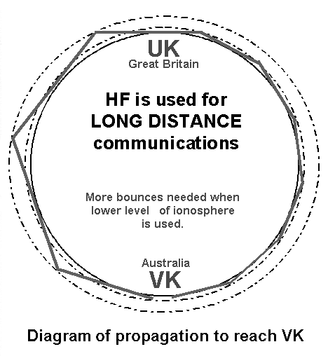
It is the ionisation of the gases, caused mainly by ultra-violet rays from the sun, that makes them partially conductive and which gives the ability to refract (reflect) the HF radio waves back to earth. This "bouncing back and forth can happen several times, for instance to reach Australia with losses in signal strength each time.
The F - layer is said to have 2 layers, F1 and F2, with F2 the highest.
5B2 Recall that the level of ionisation changes with the time of day, the time of year, and according to the, approximately, 11-year sunspot cycle.
The amount of ionisation that occurs is dependent upon :-
- the time of day
- the time of year (season) and
- changes in sun spot activity in its 11 year cycle.
The sun spot activity is an indicator of solar activity. The more sunspots the better the HF propagation as a result of increased ionisation.
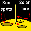
Although radio amateurs talk in terms of SUN SPOTS it is the Solar flares that cause an effect on the ionosphere. The effect of x-ray emissions from a flare is evidenced in the ionosphere as a disturbance and greater ionisation.
In November 2003 the greatest ever recorded solar flares took place and caused radio black out (amongst other effects) so too much of the sun's activities can worsen rather than improve communication.
Understand that the sunspot number is an indicator of solar activity and that more sunspots give better HF propagation as a result of increased ionisation.
Various organisations around the world monitor the sun and its sun spots
so while ionisation of the F layer is caused by ultra-violet radiation
from the sun, at night the F1 layer fades away and just the residual F2
layer remains partially ionised. This can give larger skip distances.
When we have a large number of sunspots showing the sun is quite active,
a solar flare can at anytime occur sending out the x-rays that in the daytime
cause much more intense ionisation of the F layer. This gives us
stronger HF signals reflected, and cover a greater distance around our globe.
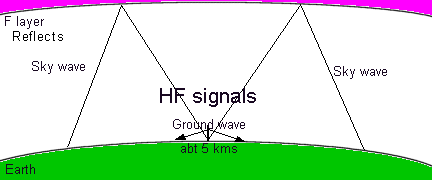
The F layer is the main mode of HF propagation but may be if you can remember that the word REFLECTS has an "F" in it standing for the F layer. ( In pure terms the use of the word Reflect is not correct, but that is the effect of the refraction of the RF in the F layer that makes signals appear REFLECTED !!!) BUT for the exam the syllabus is using the word REFLECT !!!
The word propagation means to increase the distance that your radio signal can travel over and above the distance that your radio signal can travel as a Ground Wave.
As you will see from the diagram below that the GROUND WAVE is the radio wave that hugs the earth but quickly become weaker with a ranges of a few kms at best. Thus at what ever frequency you are operating in the HF bands any distance you achieve is dependent upon bouncing / deflecting off the "F" layer in the ionosphere.
F layer ionisation during daylight enhances propagation.
It is the F layer which plays the greatest part in HF propagation. The sun causes the ionisation during periods of daylight with a peak in the early afternoon (local time).
F layer looses much of its ionisation during night particularly at the higher HF frequencies.
Whilst the F layer remains ionised over night it is much weaker than during the day and hence propagation at night dwindles on the higher HF bands.
In Winter F layer remains relatively constant at the daylight levels
During the winter the ionisation tends to remain higher as the WX (weather) gets colder.
F layer has enhanced propagation during sun spot activities
During the 11 year sun spot cycle the more sun spots there are the higher the ionisation which lead to better reflection and the higher the radio frequency that can be reflected.
Recall that the highest frequency that will be refracted over a given path is known as the Maximum Usable Frequency (MUF).
During intense F layer ionisation higher frequencies of RF become able to reflect around the world. When we operate our radio equipment we can only transmit and receive over distances that the F layer allows us to do, which is constantly changing during night and day. The highest frequency we can use is called the MUF or Maximum Useable Frequency.
5B3 Recall that the F2 layer provides the furthest refractions for HF signals (about 400km) and that the F layers combine at night.
F2 layer can be between 200km and 800km but averages out at around 400km. At night when the ionisation of the F1 layer fades away the 2 (F1 and F2) combine to form only one layer. Higher frequencies can no longer reflect so just the lower frequencies can be used for communication.
Recall that multiple hops permit worldwide propagation.
Long distance communication is possible when using HF frequencies as the radio waves bounce back to earth off the ionosphere. Worldwide communication requires several bounces between earth and the ionosphere and this propagation depends on how well the ionosphere bends or reflects the radio waves back to Earth.
Understand how fading occurs and its effect on the received signal.
Radio signal fading refers to the variations in signal strength that occur due to interference from obstacles, atmospheric conditions, and multipath propagation, where signals take multiple paths to reach the receiver. This phenomenon can significantly impact communication quality.
Recall that Short Path ionospheric propagation of HF signals is the most direct route around the earth.
Short path propagation of HF radio signals involves the direct transmission of signals between two points usually where the strongest ionisation occurs in the atmosphere.
Recall that Long Path ionospheric propagation is where HF signals are received via the opposite route around the earth to the Short Path.
As some partial ionisation remains in the F2 layer at times, or happens during the transition from night to day, there is a possibility for signals to take a longer route around the world. This is called long path communications. This is usually the opposite way round the world to short path.
5B4 Recall that the D layer tends to absorb the lower radio frequencies during daylight hours and that it tends to disappear at night.
The D layer is the most dense of the ionised layers and is the closest to the earth's troposphere and thus closest ionised layer to the earth. The D layer is nearest to the earth at about 70kms. During intense radiation from the sun it can have a blocking effect due to absorption, rather than reflecting, on many HF frequencies.
Recall that the lowest frequency that can pass through the D-layer without significant absorption is the Lowest Usable Frequency (LUF).
Because of the dense ionisation, the D Layer absorbs the HF signals, and just allows some propagation at very low frequencies. Now radio contacts can only be achieved without being absorbed up to a certain frequency which is known as the LUF (lowest useable frequency).
Understand that if the D-layer absorption (LUF) occurs at frequencies higher than the MUF then no ionospheric propagation can occur.
In an area where the LUF is higher than the MUF, then ionosphere propagation no longer takes place. Then we have what is called a "radio blackout" until such time as the D Layer weakens. This can have an effect on all communications such as aircraft, satellite, and shipping, etc.
5B5 Recall that in addition to VHF, waves
in the in the 24 MHz and 28 MHz upper HF band can also
occasionally be significantly increased by refraction from
highly ionised areas in the E layer (Sporadic E).
Recall that the height of the E layer will support a
single hop of up to about 2000km and that multi-hop
propagation can occur.
E LAYER and Sporadic E enhance VHF and UHF
Propagation of the signals at VHF and UHF frequencies are within in the troposphere which is located below the ionosphere.
If no propagation takes place in the troposphere then the VHF and UHF signals are passing into and out of the ionosphere and thereafter are lost into space.
If you have success with DX communication on VHF and UHF then is will be because of the enhanced propagation due to tropospheric ducting. E Layer propagation happens when signals go up to 2000km on a single hop or more as multiple hops can sometimes happen.
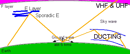
VHF and UHF can sometimes get reflected like HF when the "E Layer" becomes highly ionised - and the signals are reflected back to earth. Because the effect is not uniform it can be considered as sporadic - hence "Sporadic E" propagation.
If you look at the weather forecast on the TV you will often see a simplified version of what is called a synoptic chart such as is shown below.
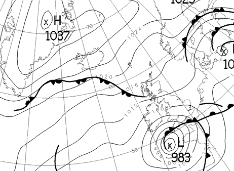
You can see on the chart the letter H and the number 1037 below and L and the number 983 below. The H represents the high pressure area and the L the low pressure area. The numbers relate to what is called a barometric pressure - but you do not need to know any details other than understanding that there is a difference between HIGH and LOW Pressure in the atmosphere.
These HIGH and LOW pressure areas are also called a High pressure system and a Low pressure system. So with that background in mind let's deal with the effect of the High pressure system.
Ducting is the enhancement of VHF and UHF
When there is high atmospheric pressure, as explained above, enhanced VHF and UHF propagation can occur by what is called "Ducting" in the troposphere.
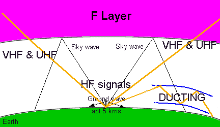
The troposphere is the layers of atmosphere below the
ionosphere.
The orange coloured lines represent the VHF and UHF
signals which are not reflected or refracted by the F layer but if the
signal does get trapped in the troposphere then it is "ducting" that
enhances the propagation as if it were flowing through a large
pipe.
The basis of ducting is that the VHF and UHF signals get trapped between two layers of the troposphere or between the ground and a layer of troposphere and then are released in a hole in the ducting at a much further distance than is normally expected of VHF and UHF propagation.
From the UK ducting across the North Sea water surface may allow microwaves communication with the Netherlands but the path soon disappears at a cliff face even a modest one where the signal is forced up out of the duct.
VHF and above
5C3 Recall that at VHF and above, multipath propagation can occur where signals are reflected off objects (such as a buildings or aircraft) and the reflected signal is received in addition to the direct, un-reflected, signal.
Multipath propagation of radio waves occurs when a transmitted signal takes multiple paths to reach a receiver, due to reflections, refractions, and diffractions caused by obstacles such as buildings, hills, and the ground. This can lead to several copies of the same signal arriving at slightly different times, which can cause interference and variations in signal strength. While multipath can enhance signal reliability in some cases, it can also result in issues like fading and signal distortion, making it a critical factor to consider in radio design.
A fact that you need to know is that Snow, ice and heavy rain can attenuate (reduce the signal strength) of UHF and higher frequency signals.
The origin of some of the text on this page is from the RSGB with additions by the web master