

Transmitters and Receivers
Microphone amplifiers and modulators
3E1 Recall that a Balanced Modulator is used to produce two sidebands whilst suppressing the carrier.
SSB (Single sideband) is a special form of AM where one sideband and the carrier have both been removed from the transmitted signal leaving one active sideband. See the similarity in the diagram below which are derived from the AM signal diagram.

SSB makes more efficient use of the power from your transmitter as power is not used to transmit the carrier and the other sideband because the signal is without the carrier and one side band, both are suppressed by filtering, the transmitted signal takes up only half the bandwidth, e.g. 3 kHz not 6 kHz.
![]() So what happens to the
carrier and other side band? They are both suppressed by the
rig's filtering and then put back in by the receiver hearing
the signals.
So what happens to the
carrier and other side band? They are both suppressed by the
rig's filtering and then put back in by the receiver hearing
the signals.
You must understand that a CW signal occupies the least bandwidth as there is no modulated audio signal and that FM occupies the most bandwidth due to the nature of the signal.
3E2 Understand that an SSB filter is a Band Pass Filter that will only allow one sideband to pass to the Power Amplifier.
A very narrow band-pass filter is used to suppress the carrier and the "other" sideband leaving the required sideband for transmission. In a receiver, one way the received sideband signal is converted back to audio is by re-inserting the carrier then passing to an A.M. detector circuit. Lower sideband or upper sideband are usually selected in the transceiver by a switch which selects a different band-pass filter for each sideband.
Recall that in an analogue transmitter, SSB filters are normally constructed from a number of quartz crystals or other resonators.
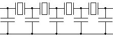
Above is the diagram of a type of crystal filter
The crystal filter uses a piece of quartz crystal exactly like a typical crystal used for stable frequency generation. The crystal is usually combined in a circuit with inductors and capacitors to give an impedance match between the stages of amplification that the filtering is applied to.
In practice, because a single crystal is a very high "Q" device (and hence possesses a very narrow bandwidth), it is usual to build a crystal filter that incorporates several crystals. These crystals are all carefully chosen such that they are not all on the same frequency, but spread on, and around the centre frequency of the filter.
In this way, a wider bandwidth for the filter may be obtained, whilst still maintaining the very steep "sides" of the filter characteristic.
3E3 Recall that a variable capacitance diode can be used in an oscillator to produce frequency modulation (FM).
Frequency modulation of a carrier is somewhat simpler than an AM or SSB signal as it can be carried out in the early stages of the Tx. By adding a variable capacitance diode ( also know as a varactor diode ) to the fundamental oscillator tuned circuit, modulation takes place by connecting the microphone audio signal (usually through an audio filter) to the varactor diode.
The diode is biased such that both the positive and negative peaks of the modulating wave form are both linear and equal. The higher the applied voltage the lower the resulting capacitance and vice versa. Greater deviation of the FM signal is produced by increasing the amplitude ( and thereby the voltage ) of the audio coming in from the microphone.
Deviation for a broadcast station is typically ±75 KHz, but in our amateur
world the bands are narrow, so we use a peak deviation of ±5 KHz where 25KHz
channels spacing is used or ±2.5 KHz peak deviation where the channels are
spaced 12.5 KHz. For calculations the formula from the formula sheet is
 which stands for :-
bw = bandwidth AFmax = Maximum Audio Frequency Δf = peak deviation
So if you were given a peak deviation of 5kHz and maximum audio frequency of 3.5kHz the band width (bw) would be:
bw = 2( 5 + 3.5 ) = 2( 8.5 ) = 17Khz
There is another quantity when dealing with FM called the Modulation Index which helps us understand if the signal is classed as narrow-band or wide-band. It is the ratio of the peak deviation to the maximum audio frequency. It is written as:-
Modulation index = Peak deviation ÷ Maximum audio frequency. The value can be written as h or υm = δmax ÷ mf
For FM broadcast this value is around 5 showing wide-band FM and in amateur circles its value is around or less than 1 showing it is narrow-band FM.
RF power amplifiers
3F1 Understand the concept of the efficiency of an amplifier stage and estimate expected RF output power for a given DC input power, given the stage’s efficiency.
Firstly what is linear amplification?
We are not talking about an add on Amplifier but the part of the transceiver which increase the power of the modulated signal to the output power required say up to 100 watts
Linear amplification takes the input signal and duplicates it exactly and provides an output that may be several times or even hundreds of times larger than the input power.
Which modulations require linear amplification ? AM and SSB
Because of the nature of the wave forms both AM and SSB have the amplitude of the wave form at input directly related to the amplitude of the wave form at the output.
If the input wave form is not replicated perfectly at the output and so is distorted on output so will be the audio signal received by the distant station be distorted. The distortion could be so severe that it creates harmonics of the input signal which fall outside the desired band width and your signal could therefore fall outside the amateur bands causing interference.
Which modulation does NOT require linear amplification ? FM and CW
As the FM signal has no amplitude component part which as shown above can causes distortion, and it is only the FREQUENCY that is changing there is NO NEED for a linear amplifier. CW is just on off keying of the carrier again with no change in amplitude there is NO NEED for a linear amplifier.
However in a power amplifier, there are three types of amplification which are labelled class A, which has an efficiency around 35%, class B which has an efficiency of 50%, and class C which has an efficiency of 60%. This efficiency is the ratio of input power compared to output power produced.
We can use our ohms law triangle to calculate this from the d.c. power supply, say 12v, and the current drawn from the amplifier, say 15 Amps, gives us 12 x 15 = 180 watts input power. So if a class A amplifier, we can produce 180 x (efficiency of 35%) = 63 watts power out.
Transmitter interference
3G2 Recall that oscillators, mixers and amplifiers can produce harmonics which are multiples of the fundamental frequency.
A harmonic is a waveform whose frequency is a multiple of the fundamental .e.g. x2, x3, x4 etc.
In addition the frequency that oscillators, mixers and amplifiers are designed to operate at, which is referred to as the fundamental or first harmonic, they also can produce additional harmonics i.e. numerical multiples of the fundamental frequency.
![]() Please note that the actual frequency
is the 1st harmonic and that other harmonics are when actual
frequency is multiplied by a whole number.
Please note that the actual frequency
is the 1st harmonic and that other harmonics are when actual
frequency is multiplied by a whole number.
The frequency of the harmonics is dependent upon how many times the fundamental frequency, (or sometimes called the first harmonic frequency) is multiplied by a whole number. The harmonics are referred to as the second, third, forth and for this course up to the fifth harmonic.
Thus:-
The fundamental frequency or first harmonic x 2 = second harmonic
The fundamental frequency or first harmonic x 3 = third harmonic
The fundamental frequency or first harmonic x 4 = forth harmonic
The fundamental frequency or first harmonic x 5 = fifth harmonic
For example, if the oscillator is designed to work at 3.5 MHz, then:
-
First harmonic or fundamental is 3.5 MHz.
-
Second harmonic 3.5 MHz x 2 = 7 MHz
-
Etc.
In the exam, questions could be asked where numerical calculations of the harmonic frequency are required such as :- What is the fifth harmonic of 50.15MHz
Answer 50.15 x 5 = 250.75MHz.
Recall that harmonics can cause interference to other amateur bands and other radio users.
Frequencies that are transmitted other than the wanted frequency, such as harmonics of the wanted frequency, could cause interference to other amateur bands users and other radio frequency users.
3G3 Recall that a filter is a device that blocks some frequencies and passes others. Understand the effects of low-pass, band-pass and high-pass filters.
Understand that a low-pass filter, a band-pass filter and a band-stop (notch) filter can minimise the radiation of harmonics.
Transmitters can produce unwanted signals even when care has been taken with their design. If these unwanted signals are radiated strongly enough to cause interference to RF users one or more filters is needed to eliminate or at least reduce the level of the unwanted signals. The filter needs to be designed to pass as much of the wanted signals as possible.
There are three filter you need to be familiar with for this course:-
-
Low Pass
-
High Pass
-
Band Pass
For the purpose of this course the filters are constructed from inductors (L) and capacitors (C) and hence are referred to as LC filters. The filter is in fact a "tuned circuit"
Filters can be described as passing some frequencies and stopping other hence the expressions "pass band" and "stop band". In a perfect world the filter would:-
-
pass unhindered all frequencies within the pass band but in fact they are reduced slightly and
-
stop all frequencies within the stop band but in fact they are only much reduced.
The frequency where the pass band and stop band meet up is called the "cut-off frequency" (fc) of the filter.
A low pass filter (LPF) passes frequencies lower than the cut off frequency
A low pass filter (LPF) is designed so that it passes frequencies that are lower than that of the stop band so in effect signals above the cut-off frequency (fc) are reduced. The Low Pass Filter is therefore use with a radio transmitter to reduce as far as possible harmonics of the transmitted frequency.
In the next animation a plot of the harmonics is overlayed the output frequency to show how the fundamental frequency is hardly affected by the low pass filter but the harmonics 2 through to 5 show significant reductions in output level (amplitude).
You will be pleased to learn that many HF, VHF, and UHF transceivers have a low pass filter built in.
A high pass filter (HPF) passes frequencies higher than the cut off frequency
A high pass filter (HPF) is designed so that it passes frequencies that are higher than that of the stop band so in effect signals below the cut-off frequency (fc) are reduced.
A band pass filter (BPF) passes frequencies between the cut off frequencies
A band pass filter (BPF) is a combination of low pass and high pass filter that will passes a range of frequencies in the pass band, any frequencies above or below this range are reduced. Unlike the LPF and the HPF, the BPF has two stop bands and two cut-off frequencies (fc) at the meeting points of each of the stop and pass band.
Remembering which circuit diagram refers to which can be a daunting task for some students. So try to remember just one and the other should then fall into place.
Think of the inductors at the side of the filter as springs on a lifting bridge that can operate to allow a high bus to go through the HIGH PASS filter.
Then look at the low pass filter and the capacitors could be like bricks of a low bridge that cannot stretch and so will not allow the bus through.
Recall that RF power amplifiers can produce harmonics of the wanted signals and that suitable filtering is required to avoid harmonic radiation.
Any r.f. power amplifier can produce harmonics because of the way the circuits are designed. We know that class C amplifiers have the largest amplification factor so harmonics can be created, thus filtering is essential after these stages. Class A amplifiers have careful design and generate less harmonics, but they still need to be followed with filters. All filters need to be designed so that harmonic output is below a certain level.
3G4 Understand that too fast a rise and fall time of the transmitted RF envelope of a CW transmitter may cause excessive bandwidth (key clicks) and that this can be minimised by suitable filters in the keying stage. Recognise a diagrammatic representation of rise and fall time.
When a morse key is opened and closed to operate a CW Tx too fast a rise and fall time of the transmitted RF envelope of a CW transmitter may cause excessive bandwidth a problem known as key clicks. The clicks are a large number of audio frequencies caused by the sharp edge of the wave form shown below in RED.
Key clicks can be minimised by suitable filters in the keying stage.
Note : In the red diagram the very sharp corners to the shape which cause key clicks whilst in the blue diagram the corners have been rubbed off giving slower rise and fall times and reduces / eliminates key clicks. This is achieved by a carefully designed CW filter.
The animation merely show the change from the original to the improved wave shape.
3G5 Recall the cause and effect of ‘chirp’ and identify suitable remedies.
Put simply, chirp is a change of frequency that has upwards or downwards shift. In the amateur radio world chirp can be a nuisance as when detected audibly it can sound like a bird chirping away in the background of a receiver.
This chirp can occur when a CW key is depressed or released, so causing a change by the extra power drawn to process the signal causing a voltage drop in the power supply voltage. This causes the oscillator circuits to change frequency slightly. We can somewhat fix this issue by careful voltage regulation in the power supply and robust and stable oscillator circuitry.
In industry chirp can be useful and is generated by modulating a carrier with a sawtooth wave forcing chirp. This application is widely used in lasers, optics, radar, sonar, and other uses.
The origin of some of the text on this page is from the RSGB with additions by the web master