Bredhurst Receiving and Transmitting Society |
Part 4 |
||||
|
|||||
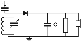
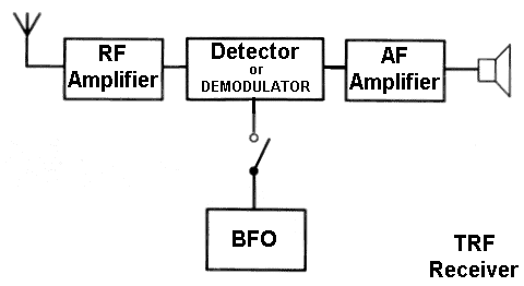
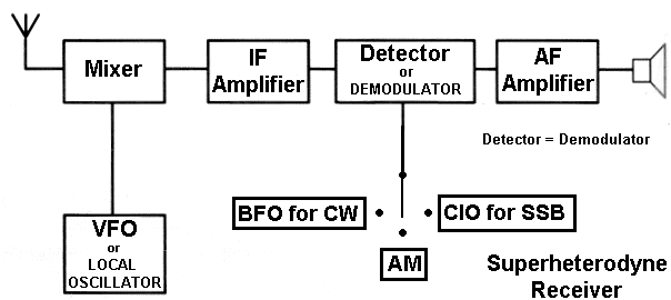
Before we go into this part of the course there are some very easy marks to be gained by learning the diagrams below. Some students make up cards with the diagrams on opne side but on different cards a different section left unmarked and on the reverse side it states which part is missing. They then use the cards so that they can check / test their knowledge easily. 4f Simple block diagram of receivers 4f.1 Understand the block diagrams of the crystal diode receiver, tuned radio frequency (TRF) or straight receiver and superhet receiver. The crystal set Place mouse pointer on diagram to see wave forms The full circuit diagram of a crystal set which is an "AM radio signal receiver"
Thus the crystal set is a "radio signal receiver" (or just "receiver") in its simplest form and was used almost when AM radio broadcast transmissions started. The diode shown above is a modern day substitution for a piece of crystalline material (galena) and a fine wire known as a 'cat's whisker'. The fine wire had to find what was called the "sweet spot" on the galena else no radio station could be heard (as it would have been the same as taking the diode out of the circuit). Finding the right spot on the galena was so critical that even changes due to slight vibration lost the signal. Those were the days of so called "Real Radio". Today we have the easy way out as manufacturers have developed the diode and a crystal set can easily be made from simple to obtain components. So how does it work? The RF signal (RF energy) is picked up by the antenna, as it is in all receivers, and goes into the tuned circuit. The circuit diagram above shows a parallel tuned circuit, which can be tuned to the desired radio station (frequency) by the variable capacitor. At the resonant frequency, the parallel tuned circuit has a high impedance (or opposition to AC / RF currents), the effect of this is to generate a maximum AC / RF potential difference across the tuned circuit. The potential difference is rectified by the diode and DC is smoothed out by the capacitor C. The end result is that the recovered audio is only the overall shape of the signal which is applied to the ear piece / headphones which would have been the same shaped audio signal used to modulate the transmitter hence you hear what was transmitted. Simple Eh!! The TRF
The Tuned Radio Frequency receiver is for AM signals and with the BFO ( beat frequency oscillator switched in can also receive CW signals. RF Amplifier TRF has a RF Amplifier (also called a Radio Frequency Stage or (RF) Stage). This stage amplifies the incoming signal from the antenna before it passes it to the detector or demodulator stage. The detector ( also call the demodulator) The detector recovers the AM signal and operates on the same principal as the crystal set but has the advantage that the an amplified signal is provided by the RF amplifier stage. Then the recovered audio is passed to the Audio Amplifier stage. Audio Amplifier The Audio Amplifier stage simply makes the recovered audio signal louder so that it is sufficient to hear in a loudspeaker. BFO The detector mixing with the BFO recovers the CW signal As mentioned above the detector recovers the AM signal and with the BFO switched in a CW signal can be resolved. Then the recovered audio is passed to the Audio Amplifier stage. The Superhet Receiver
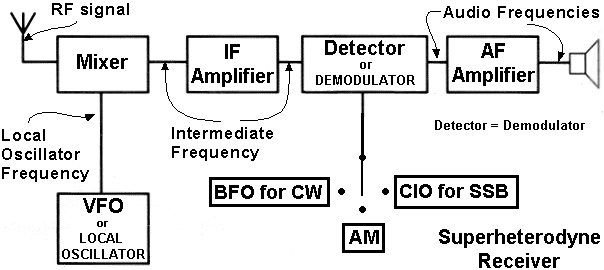
This is the superhet receiver a receiver which in its basic form receiver AM signals and by switching in a CIO (carrier insertion oscillator) can also be used to receive SSB signals or by switching in a BFO (Beat Frequency Oscillator) can also receiver CW signals. How it works is perhaps best understood by considering each stage it turn as is done in the next part of the syllabus. 4f.2 Understand the functions of the RF amplifier, mixer, local oscillator, IF amplifier, demodulator (detector), and audio amplifier. RF Amplifier (This is not in the drawing provided in the syllabus but as it is in the text of the syllabus as given above).
Mixes the wanted amplified RF signal with the VFO signal (or as it is sometimes
stated, with the local oscillator signal to produce sum and difference
frequencies of the RF signal and the LO signal which in fact are modulated
identically to the incoming signal.
The LO is the VFO which generates an RF signal for use by the mixer.
Intermediate Frequency Amplifier (IF)
Provides the main amplification and includes a filter, which removes adjacent
signals and wrong mixing products
The demodulator recovers the modulating audio signal
when used with the BFO (beat frequency oscillator) can recover CW signals
when used with a CIO (Carrier insertion oscillator) can recover SSB signals
Amplifies the signal to drive a loudspeaker.
4g Intermediate frequency
4g.1 Recall that the intermediate frequency is the
sum of or difference between the RF and local oscillator frequencies.
The intermediate frequency is created by either:-
Adding the frequency of the local oscillator to the RF or Subtracting the
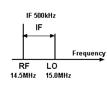
RF from the Local Oscillator frequency (or if the local oscillator frequency
is greater than the RF subtracting Local Oscillator frequency from the RF
frequency).
The INTERMEDIATE FREQUENCY is the sum of
or difference between the RF
and LOCAL OSCILLATOR FREQUENCY.
Putting that another way the Intermediate frequency differs from the RF frequency
by the value of the local oscillator by either addition or subtraction of
the local oscillator frequency.
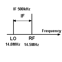
Have a look at the diagram below.
Here you may be asked to do some relatively simple calculation.
For instance with the RF and LO frequencies expressed in MHz to one decimal
place the answer will be required in kHz.
A calculation like this may be asked :-
What is the IF if the RF is 7.1MHz the LO 6.6MHz
thus 7.1 - 6.6 = 0.5MHz = 500 kHz
There is also the possibility that the IF could be the sum of the RF and
LO as in HF receivers where a first IF exists well above the tuning range.
You do not need to understand why this is done in the Intermediate Licence
course and thus is it is not a possible exam question.
4h Frequency selection
4h.1 Recall and understand that tuned circuits in RF
and IF amplifiers select the wanted signal.
It is the tuned circuits in the RF and IF amplifiers that select the signal
that you eventually hear in the loud speaker.
RF amplifiers are often what is called "fairly broad band" and thus quite
a few stations signals will be mixed down to the IF. Then the much narrower
IF tuned circuit selects the one wanted signal.
4i Detectors
4i.1 Understand how a diode detector will recover the
audio from amplitude modulated signals. Understand that to generate the audio
for CW signals a beat frequency oscillator (BFO) is used; for the recovery
of single side band audio, a carrier insertion oscillator (CIO) is used;
for the recovery of FM audio, a discriminator is used.
Diode AM detector
The simple diode AM detector operates on a similar principal to the simple
rectifier diode, in that the diode allows the signal to flow in only one
direction and just like when dealing with an AC signal which what an Audio
is, it removes the lower half of the signal. The output is related to the
instantaneous amplitude of the amplitude modulated transmission. In other
words you hear a copy of the audio that causes the modulation in the first
place.
For CW detection to generate the audio a Beat Frequency Oscillator is needed
For the recovery or detection of SSB a Carrier Insertion Oscillator is needed.
For detection of an FM signal a frequency discriminator is needed
For the AM simple detector to demodulate a FM signal, a frequency discriminator
used.
In summary for:-
AM needs diode
CW needs diode and BFO ( beat frequency oscillator
)
SSB needs diode and CIO ( carrier insertion
oscillator )
FM needs diode and frequency Discriminator.
4i.2 Recognise and identify the waveforms produced
in a diode AM detector.
Place mouse pointer on graphic to see
animation
The AM modulated RF comes in via the aerial is rectified by the diode and
the capacitor smoothes it all out to become the recovered audio.
4j AGC
4j.1 Understand that
the automatic gain control (AGC) of a receiver operates by sensing the strength
of the received signals at the detector and adjusting the gain of the IF
and sometimes the RF amplifiers to keep the audio output level fairly
constant.
If you have done any SWL (short wave listening) you may have noticed that
the signal level that you hear remains fairly constant. This is almost certainly
due to the AGC or Automatic Gain Control in the receiver circuit that has
an effect on the speaker volume.
The strength of the signal at the detector is used to control the gain of
the IF amplifier (and also some times the RF amplifier) so the weak signals
are amplified more than stronger signals before they are passed to the
loudspeaker..
The effect is that you hear sounds of approximately equal loudness. This
avoids the signal going too quiet or too loud and requiring you to turn the
AF control up and down all the time. Clever eh !!
|
|||||
|
|||||

