

Technical Basics
Feeders
4A1 Understand the equal and opposite currents
flowing in a balanced feeder cause equal and opposite fields
around the two conductors.
Coaxial feeder is an unbalanced feeder
Coaxial feeder or coax as it is know for short is a cable which as a generalization looks on the outside like any other round cable. Whilst the basic construction of the cable remains the same it size can vary from a few mm diameter up to say 50mm depending upon the frequency it is to be used.
It is only when you open it up that you see the construction.

There is an inner core which carries the signal, then a layer of polythene or air spaced dielectric, on top of that is an outer braid which for good quality coax is woven to a tight weave so that there is minimum leakage, and lastly an outer jacket which provides waterproofing and resists damage of the internal parts. The outer jacket must be intact else any ingress of water / moisture and the cable will be damaged.
Twin feeder on the other hand is a much simpler type of cable being merely two conductors equally spaced along their length. The conductors carry equal and opposite signals. The spacing of the conductors is a deliberate part of the construction.
The wires can be thin say 1mm or up to say 5mm depending upon the conditions that they are to work in.
Uses of the feeders
Twin feeders also called balanced feeders
Twin feeders can be used for feeding dipoles and are most usually used for frequencies up to 30MHz.
Coaxial feeders
Coaxial feeders can be used with frequencies up to the 1GHz but then the feeder is usually a wave guide.
Coaxial feeders can be used to feed dipoles with baluns, yagis and vertical antennas.
Understand that these fields cancel out, but that nearby objects can cause an imbalance that makes the feeder radiate RF energy.
![]() Some
students may still confuse balanced and unbalanced feeders. If you
have any doubt which is which start from the top of this page
again.
Some
students may still confuse balanced and unbalanced feeders. If you
have any doubt which is which start from the top of this page
again.
Balanced feeder, or twin feeder as it can also be called, neither of the conductors is screened so each could radiate. As any radiation from the conductors is equal and opposite they cancel each other out.
There is a proviso here in that if conducting objects are close to the feeder and especially if much closer to one conductor than the other then the radiation would not be in balance nor symmetrical and radiation is not cancelled out and stray radiation could occur. Thus there is a need to keep twin feeder away from walls and other objects.
Coaxial cable on the other hand does not suffer from the problems of changing radiation pattern due to the proximity of local objects as the screen wrapped over the dielectric prevents the inner signal carrying conductor from radiating and may be run along walls or even buried under ground.
Recall that a rectangular waveguide must have its larger dimension greater than λ/2 for the signal to travel.
A rectangular waveguide is used mostly for frequencies of 1GHz and above and must be at least aλ/2 for the signal to travel inside. Should the waveguide be a smaller size the signal would not get through. Therefore the size of the waveguide is governed by the frequency of the signal.
4A2 Recall that twin feeder usually has lower loss than coaxial cable.
All types of feeder do not deliver at the end of the feeder run the same amount of power that was put in at the beginning. Such reductions in transmitted power of the signal at the antenna and reductions in signal strength on the S meter on receive are called "feeder losses".
There are several factors associated with feeder losses:-
- TRANSMIT and RECEIVE - Losses are exhibited on transmission and reception.
- LENGTH of feeder - double the feeder double the loss.
- FREQUENCY - the higher the frequency being used the greater the loss.
FACT - Twin feeder losses are much less than those for coax. In very high power broad cast transmitting station long twin feeder runs are mounted on poles similar to telegraph poles.
Thus using twin feeder for amateur use makes sense because of its lower losses.
![]() So
whilst losses do exist on reception they are more easily
understood as affecting transmissions as they can be more
readily measured. If you place a suitable power meter at the
far end of the cable and having the meter terminated in a
suitable Dummy load the amount of power reaching the end of
the cable can be read on the meter's scale.
So
whilst losses do exist on reception they are more easily
understood as affecting transmissions as they can be more
readily measured. If you place a suitable power meter at the
far end of the cable and having the meter terminated in a
suitable Dummy load the amount of power reaching the end of
the cable can be read on the meter's scale.
![]() Note also that data sheets / catalogues can give figures for
cable losses and they are often shown as losses per 100 metre
and at a quoted frequency.
Note also that data sheets / catalogues can give figures for
cable losses and they are often shown as losses per 100 metre
and at a quoted frequency.
Recall that loss is measured in dB.
Feeder loss are quoted in dB where dB stands for "decibel". For this part of the syllabus you have to be able to calculate the power delivered to an antenna for a given output from the transmitter and for given feeder losses. The calculations are not complex and are limited to multiplies of 3dB.
What you have the understand that a 3dB loss represents a half of power reaching the antenna and a 6dB loss represents only a quarter of the power reaching the antenna.
Understand the relationship between RF output power, feeder loss and power delivered to the antenna.
Calculate the unknown quantity given the other two.
Feeder loss will be in multiples of 3dB and 10dB.
![]()
Example 1 If you have a 50 watt output power and a 3dB loss in the feeder what power is expected at the antenna?
3dB loss is a half of the output power at the antenna
so 50 / 2 = 25 watts at the antenna.
Example 2 If you have a 40 watt output power and a 6dB loss in the feeder what power is expected at the antenna?
6dB loss is a quarter of the output power at the antenna
so 40 / 4 = 10 watts at the antenna.
In the same examples, if the feeder loss is 10dB then the 50W output is 5W at the antenna, and the 40W is 4W at the antenna. So a 10dB loss is a divide by 10.
4A3 Recall that feeders have a characteristic impedance which depends upon the diameter and spacing of the conductors.
The term 'impedance' can be thought of as a form of AC resistance.
In the electrical theory section we have given you an insight into resistance and associated calculation. There is another type of resistance called impedance when associated with AC circuits. The term impedance comes from the word impede meaning to resist and is used with the AC circuit to differentiate from the resistance used in a DC circuit.
![]() Reactance - more info from
this link
Reactance - more info from
this link
The aim of this section of the syllabus is to ensure that you are aware that different feeders exist and that using the correct one matters.
The characteristic impedance of a feeder is dependent upon :-
- Coaxial the ratio of the diameter of the conductors "d" "D"
- Twin feeder the ratio the spacing of the conductors and the diameter "S" "d"
For this level you do not have to know how this relationship works.
With regard to coax feeder the impedance is determined by the ratio of the diameters of the diameters of the centre and the screen. Thus a coax feeder that has bigger diameters in the same proportion will still have the same impedance but the advantage is that the larger diameter cable will have lower loss.
Recall that this impedance determines the ratio of the RF RMS potential difference to the RF, RMS current in a correctly terminated feeder.
When the feeder Characteristic Impedance is terminated by a resistive load i.e. coax 50 ohms feeder and a load of 50 ohms then Z impedance is determines the ratio of Vrms / Irms in the feeder.
Recall that for amateur use 50Ω coaxial feeder is normally used; that coaxial cable for TV and satellite receivers has a different impedance of 75Ω.
The usual coaxial feeder for Amateur to use is 50Ω where as that for TV and Satellite receivers is commonly 75Ω to 600Ω
A balanced feeder is commonly available from 75Ω to 600Ω.
Baluns
4B1 Recall the construction and use of choke type baluns.
There are several types of baluns but here we deal with the choke balun. Explanation follows....
The Choke Balun is where about 10 turns or more maybe at a diameter of about 150mm coaxial line is formed into a coil at the antenna feed point. This is best used at lower HF frequencies as at higher frequencies it loses it effect of choking off the current flowing down the "OUTSIDE" of the feed line.
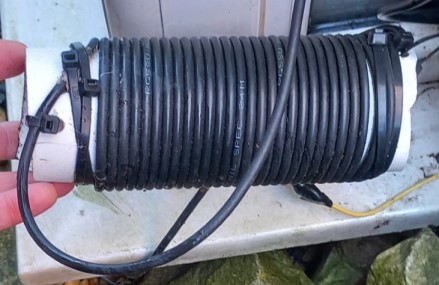
Choke Balun photo, courtesy of Nigel M0OQU
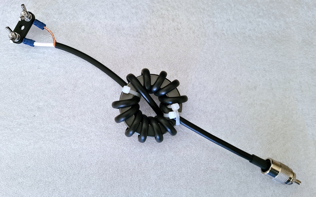
Choke Balun photo, courtesy of Charlie M0PZT
This type of balun has a wider range of frequencies and is used again to prevent any stray RF from travelling back down the co-ax to the transmitter. Balun is short for Balanced to unbalanced, and here you can see the balanced line or twin line feeder would be attached at the top of the photo and then the co-ax which is unbalanced is wrapped around a toroid, 6 turns in one direction and 6 turns in the opposite direction which would cancel out any stray RF. The output of the co-ax is then terminated with a PL259 plug which is a normal connector for HF signals. The photo is kindly provided by Charlie M0PZT at Ham Goodies at https://www.hamgoodies.co.uk. (Lots of nice radio accessories to be found there.)
The origin of some of the text on this page is from the RSGB with additions by the web master