

Fundamental theory
Resistors
2A1 Recall that components have tolerances, and that the measured value of a component may not precisely agree with its marked value.
We learned a little about resistors in the Foundation self-training course....
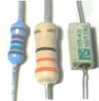
If we take the middle resistor in the picture, it has 4 bands. The orange, orange, black
show the nominal value of its resistance measured in  (ohms symbol). We work out that value at another time but here it is 33 ohms. The 4th band shows the resistor's
tolerance, or variation value from the nominal value. In this case it is the gold band which means 5%
tolerance. This means the 33 ohms nominal value really means it could be plus or minus 5 per cent so it could be
any value between 31.35 and 34.65 ohms.
(ohms symbol). We work out that value at another time but here it is 33 ohms. The 4th band shows the resistor's
tolerance, or variation value from the nominal value. In this case it is the gold band which means 5%
tolerance. This means the 33 ohms nominal value really means it could be plus or minus 5 per cent so it could be
any value between 31.35 and 34.65 ohms.
| Black | 0 |
| Brown | 1 |
| Red | 2 |
| Orange | 3 |
| Yellow | 4 |
| Green | 5 |
| Blue | 6 |
| Violet | 7 |
| Grey | 8 |
| White | 9 |
Resistor Bands Colour Code Values
The tolerance band or 4th band can be one of several colours, but the most usual ones and with their tolerance values are:
| Brown | 1% |
| Red | 2% |
| Gold | 5% |
| Silver | 10% |
Similarly most capacitors and inductors have tolerance values that deviate from the normal value, however this is not always a colour band. Sometimes the value is just printed on the capacitor casing.
Resistor Colour Code Values
If you wish to learn these color codes, it would be useful for home construction and you may get a
question on these in the exam.
How we work it out;
The resistor pictured above with the beige body has bands that are orange, orange, black, and a tolerance of gold. So we use 3 for orange and 0 for black from the table.However the third band is classed as a multiplier, so the 0 for black means no multiplier. Not so easy to follow! I have calculated this for you the value is 33 Ω and the tolerance is 5%.
Had the third band been blue the multiplier is 6, so we add 6 "0's" to the 33 to make a value of 33,000,000 Ω= 33 MΩ or if it was red the for a multiplier of 2 we add two "0's" giving us 3300 Ω = 3.3 KΩ.
Resistance
2C1 Understand circuits comprising series and
parallel connections of resistors and cells.
Calculate the value of any one of the three quantities (V, I
or R) given the other two.
Calculate the combined resistance of two or three resistors
in series and/or parallel.
Resistors of different values may be used in series or
parallel or combined series parallel circuits.
The formula for parallel resistors will be provided.
The prefixes milli and kilo may be involved for some of
these calculations.
Resistors and what they are, were introduced to you in the Foundation Licence course.
There are two quite different, and for some of you reading the course, challenging formulae associated with resistor combinations whether they are in series or in parallel
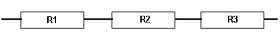
Resistors in Series
The diagram below shows resistors connected in series.
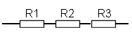
For a calculation any number of resistors, (from as few as two) may be connected as shown above.
The effective resistance of the combination of R1 R2 and R3 is given by
R(total) = R1 + R2 + R3
BUT you can of course add together as many resistors as you need to and calculate the total effective resistance of all the resistors by adding their values.
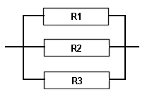
Resistors in Parallel
The diagram below shows resistors connected in parallel.
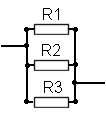
Note that all the resistors are linked to each other by the wire that is across the end of of them all so it does not matter where the other wires connect to the circuit the result would be the same.
For a calculation any number of resistors, (from as few as two) may also be connected as shown above.
The
effective resistance of the combination of R1 R2 and R3 is
given by ![]()
which can also be written as :- 1/R(total)= 1/R1 + 1/R2 + 1/R3
BUT as with the earlier example you can of course add together as many resistors as you need to and calculate the total effective resistance of all the resistors.
Let's put in some values. R1 = 100 ohms R2 = 150 ohms R3 =270 ohms
Thus 1/R(total) = 1/100 + 1/150 + 1/270
so 1/R(total) = 0.01 + 0.0066 + 0.0037
so 1/R(total) = 0.0203
so R(total) = 1/0.0203
so R(total) = 49.26
So the total resistance of R1, R2 and R3 in parallel is about 49 ohms
Note:- that the resulting resistance is always less than the lowest resistor value in the group.
However consider what would happen in a mix of series and parallel.. we have to take a stage at a time because of the complex calculations required. This is not impossible, just follow it slowly, one step at a time.

Looking at R3 and R7 they are linked in Series so total value is
150 Ω - call that R8 (100+50=150)
Now look at R8 and R6 they are link in parallel so total value is
now 60 Ω - call that R9 (parallel rule)
Now looking at R9 and R2 - they are linked in Series so total value
is 110 Ω - so call that R10 (60+50=110)
now looking at R10 and R5 they are in parallel so total value is
52.38 Ω - so call that R11 (parallel rule)
now looking at R11 and R1 they are in series, so total value is
102.38 Ω - call that R12
now we look at R12 and R4 in parallel, total becomes 50.5 Ω
with the parallel rule we get 50.5 Ω. What a lot of work, but we
completed it now.
For your exam do the calculation as shown and then compare you answer to that in the question and you will see what figure is like yours and pick that as the correct answer.
If you are weak on maths then ask your lead instructor for some extra work on this to help you learn it.
Understand the relationship between power, potential difference and current. Manipulate the equation P = V x I to find the unknown quantity given the other two. The prefixes milli and kilo may be used.
Power is measured in the unit WATT or W and in the FLC you were introduced to a magic triangle this is also needed in the ILC so that you can manipulate the equation P = V x I to find the unknown item given the other two items. Watch this:-

Practice with this until you are certain that you fully understand how to find one unknown from two know items.
NOTE: calculations in the exam may use the prefixes milli and kilo. We will see exactly what they are later.
A student from an early course suggested the following to help you remember the order of the letters :-
P = Prefers V = Vanilla and I = Ice-cream
hence
Prefers Vanilla Ice-cream
Example :- What power supply would be suitable to run a 50W transceiver from a 12V power supply?
from P = V x I
we get 50 = 12 x I
then I = 50 / 12
result 4.166 Amps
The answers given in the exam choices might be :-
A 12V at 500mA
B 12V at 1A
C 12V at 6A
D 24V at 4A
D is wrong as it is at the wrong voltage, A & B are too low so the answer is C
However be aware that the output power actually bares no direct relationship to the input power as sometimes to have an output of 50W RF you need 100W of DC input !!!
Recall that a current through a resistor results in a transfer of electrical energy to heat energy in the resistor.
Because resistance is the opposition to the flow of electrons the energy of the electrons being slowed down results in the generation of heat in the resistor. This is why resistors have a resistance value and also a power wattage rating to indicate how much power they can dissipate.
Understand circuits comprising series and parallel connections of resistor and cells.
Calculate currents and potential differences in such circuits.
The circuit below Fig1 the Resistors R1, R2 and R3 are the opposition to current flow around the circuit to find the current flowing in the circuit one must first work out the total resistance value.
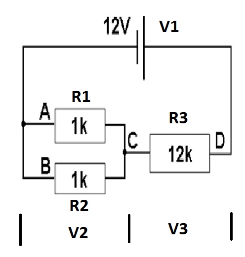
Fig1
To work out the two equal value resistor in parallel Rtotal = (R1 or R2)/2
So Rtotal = (1000)/2 R total=500 ohms
Now to work out the total resistance RT in the circuit when resistor are in series add together
RT = Rtotal + R3
So RT= 500 + 12000 = 12500.
To find the total current flow from the battery and at points C and D using Ohms law.
Itotal = V1/ RT so Itotal = 12/12500 = 960uA
To workout the voltage drop crossed R3 calling it V3 using Ohms law
V3 = R3*Itotal
V3 = 12000*960uA = 11.52V
so V3 = 11.52 Volts
To workout the voltage drop across R1 and R2 which is V2 there are a number of ways.
First way because we have worked out the voltage drop across R3
V2= V1-V3
so V2= 12 - 11.52 = 0.48V
V2 = 0.48V.
The second way because we have worked out the two resistor in parallel R1 and R2 which was called Rtotal and also the total Current flowing in Rtotal is Itotal using Ohms law V2 = Rtotal x Itotal
So V2 = 500 x 960uA = 0.48V
So to sum up the voltage drop across R1 and R2 is V2 = 0.48v, the voltage drop across V3 is 11.52v
The current through R3 is 960uA
But what about the current flowing through R1 to work this out using Ohms law because the voltage drop across R1 has be worked out V2 the current flow through R1 is V2/R1
So 0.48/1000 = 480uA
To work out current flowing through R2 is the same way has working the current flowing in R1 so V2/R2 = 0.48/1000 = 480uA
Calculate the combined resistance of two or three resistors in series. Calculate the combined resistance of two or three equal resistors in parallel.
SERIES RESISTORS
Resistance is the opposition to current flow. The bigger the resistance the smaller the current that can flow.
Before we look at the topic in electronic terms let's consider a large number of people all lined up in one long straight line.

The effort that you would need, as an electron!!, to push through would be quite a bit but not impossible.
Now what would happen if the crowd broke into two lines you would now have to push your way through the first and then the second line and you would find it more difficult and you would have used up more energy.
So if the crowd broke into three lines you would now have to push your way through all three and that would be more difficult than the other two previous examples and even more energy would have been used up.
The same is the case with resistors.

When there is just one resistor in a circuit as shown below then the amount of current flowing for a known voltage through a known resistor can be calculated based on the formula V = I x R and would be shown on the amp meter or ammeter (a ammeter in series with the circuit to measure current).
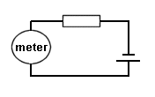
which re-arranged gives you the formula shown below.
I = V / R
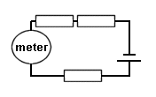
When we have two resistors in series, as shown below,
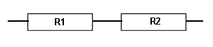
the current has to flow through both and finds it more difficult.
In fact the value of the total resistance is simply to add up the values of the individual resistors.
"SERIES Resistor TOTAL" = R1 + R2
Even though the two resistors are separated by the meter they are still connected in series.
So to find the current flowing in a circuit, through the meter, with two resistors in series you first work out the value of the total resistance and from that calculate the current from
I = V / R where R = R1 + R2
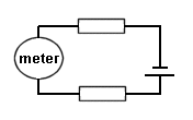
So when we have three resistors all lined up one behind the other the task of the current passing is still greater and less flows.
As with the two resistors mentioned above the total resistance is simply to add up the values of the individual resistors.
"SERIES Resistor TOTAL" = R1 + R2 + R3
Current flow
Above the three resistors are "in SERIES" as the current has to flow though each as there is no other way. also it does not matter where in the circuit the meter is to measure the current.
So to find the current flowing in a circuit with three resistors in series you first work out the value of the total resistance and from that calculate the current from
I = V / R where R = R1 + R2 + R3
Voltage across each resistor
If the voltage is measured across each resistor then the sum of these individual values will be the same as that across the battery as the set of resistors could be replaced by a single resistor equal to the total value of the individual resistors (as they are in series)
PARALLEL RESISTORS
The other way that resistors can be coupled together is for each end of one resistor to be linked to the same end of the next resistor and the same with the other end.

We now have a different situation to the "SERIES" as the electrical path, as we call it, has two routes to chose from. If each of the resistors is of equal value then it is as difficult for the current to pass through each resistor and therefore the current divides equally between the resistors.
If they are not of similar value ....... well that is for a later training course so let's just think in terms of similar values
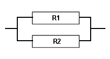
R1 = R2
Value of Two EQUAL resistors in parallel = Value of one resistor divided by 2
"Parallel Resistance Total" = R1 / 2
R1 = R2 = R3
Value of Three EQUAL resistors in parallel = Value of one resistor divided by 3
"Parallel Resistance Total R" = R1 / 3
This may look strange but if you think of it this way .... there are in the first example two paths that the current can take therefore with equal values of resistor the resistance is halved as there are two paths
and with three resistors of equal value the resistance is a third as there are now three paths!!
![]() Students
are not understanding that when faced with a question of a
current in a simple circuit that you must first determine the
value of the total resistance whether that is resistors
in series (as outlined above) or resistors in parallel as
outlined below. It is only then that you can go forward to
calculate the current flowing for a particular applied
voltage but the use of Ohm's law. So let's look in
a bit more detail about this type of question.
Students
are not understanding that when faced with a question of a
current in a simple circuit that you must first determine the
value of the total resistance whether that is resistors
in series (as outlined above) or resistors in parallel as
outlined below. It is only then that you can go forward to
calculate the current flowing for a particular applied
voltage but the use of Ohm's law. So let's look in
a bit more detail about this type of question.
![]() Current
in the circuit
Current
in the circuit
Find the current in a circuit with resistors in parallel
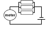
You must first find the actual total amount of resistance and from that calculate the current flowing in the circuit. The meter measures the total amount in the circuit and MUST be placed to make this reading outside the resistor network else it would only read the current passing through the single resistor with which it is in series.
Practical Example - Make a DUMMY LOAD.
Let's take a practical example. If you want to make 50 ohm dummy load then how many carbon resistors will you need and of what value to make a 40W dummy load ?
There would be several ways of going about this :-
50 0.8W 1 ohms resistors in series. That would make a fairly bulky dummy load and probably only 1W resistors available so the unit would be over rated.
So look at it another way. 2W resistor of the carbon type are available and thus 20 resistors would give us the power capability we require and assuming we are using them in PARALLEL, what value of resistor is needed ?
From the equation above :-
Resulting value = Value of one resistor / Number of resistors
rearranging the equation we get :-
Value of one resistor = Resulting value x Number of resistors
Value of one resistor = 50 x 20 = 1000 ohms or 1k ohm
So to make a simple dummy load we need 20 1k 2w resistors linked in parallel.