

2E5 Recall that an inductor will take time to store or release energy in its magnetic field.
When a current is switched on in an inductor, there is a resistance to the flow of electrons called a back e.m.f. Therefore a small amount of time is taken for the build up of energy
So with a current change there comes a change in magnetic field strength which produces the emf but in fact the emf produced opposes the change being made and is called a back emf.
Back emf is a emf produced in a conductor that tends to neutralize the applied voltage.
The slow rise of current through a large inductor when a voltage is connected across it, is caused by the existence of a back EMF (electromotive force) which is a voltage generated by the magnetic field of the inductor working in opposition to the applied voltage. The back emf is particularly large when the rate of change (frequency) of current flow is rapid, (as occurs when a circuit is switched off).
Recall that the ratio of the RMS potential difference to the RMS current as the inductor stores energy in its magnetic field is called the reactance of the inductor and is measured in ohms.
When an inductor has an a.c. applied this rapid change in back emf is magnified and as the magnetic field increases and decreases the result is call reactance.
Understand that the reactance of an inductor depends on the frequency of the alternating current and that the reactance rises as the frequency rises.
Identify the graph of reactance against frequency for the inductor.
If we draw a graph of inductive reactance  , against Frequency, we get :-
Note: Inductive reactance is considered to be positive.

We can observe from the graph how an increase in frequency causes the reactance to increase. This linear reactance is written as XL.
As we saw earlier at a.c. the voltage lags the current by 90 degrees. Due to at any one moment in a cycle they are both at differnt levels. In d.c circuits we use ohms law as R = V / I.
The way we overcome this in a.c. calculation is to use the RMS value. So now XL = VRMS / IRMS. The result is in ohms.
2E6 Recall that in a circuit comprising resistors and capacitors or inductors (or both) a current will result in energy transfer into heat in the resistors and energy storage and release in the capacitors or inductors.
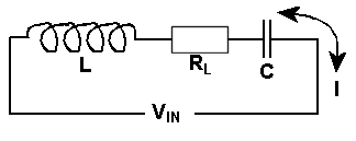
We have spoken about the reactance of the coil (inductor) which is
like resistance but the coil still has "normal" resistance and
for these calculations we call this  and identify it in the circuit diagram as a resistor.

When an a.c. voltage is applied to the above circuit, the energy through RL,the internal d.c. resistance of the coil, causes heat to be generated. In the Inductor XL the energy is stored and in the capacitor XC the energy is stored, as reactance.
Recall that in such a circuit the ratio of the overall
potential difference to current is termed ‘impedance’ and
that this name denotes an opposition to both energy transfer
and energy storage in the circuit.
In such circuits containing resistance and or capacitance and or inductance the ratio of the overall potential difference to current flowing is termed 'impedance'. This name denotes an opposition to both energy transfer and energy storage in the circuit. Note this impedance to the flow of AC is measured in ohms.
Recall impedance is measured in ohms.
Note: Phase and vector notation is NOT included at this
level.
This was mentioned earlier in the Capacitive and Inductive reactance section.
2E7 Recall and manipulate the formula v = f × λ
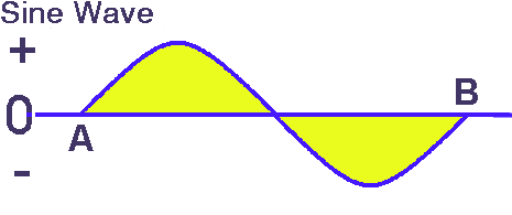
In the Foundation exam we looked at a graph of Frequency vs Wavelength. Frequency is measured in Hz (Hertz)and is designated the symbol f. It is the number of times in one second that an alternating current goes from zero to positive peak then through to negative peak and back to zero i.e. a complete whole cycle. From A to B in the diagram for the number of times it happens in a second.

The wavelength of a single cycle is A to B, but the relationship of wavelength to its frequency f,is designated by the symbol λ. Now we can calculate the velocity v of a wave from their ratio.
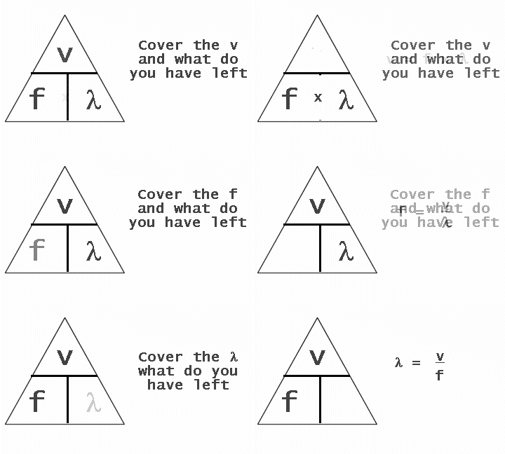
v = f x λ
where f is measured in Hertzλ is measured in Metres
v is a constant for the velocity of radio waves in a vacuum.
Calculate frequency or wavelength given the other parameter.
Given either the frequency or the wavelength we can calculte the other by transposing the equation
f = v / λ
λ = v / f
For calculations, the velocity of radio waves will be given.
Some maths for you to further your understanding of conversion of frequency to wavelength and vice versa.
In the FLC you were able to use a simple table to convert frequency to wavelength and vice versa. That table was a representation of the simple formula which enables you to calculate frequency or wavelength given one or the other.
NOTE: The use of a lower case v so that there is no confusion with an upper case V which stand for Voltage.
NOTE: The frequency f is expressed in Hz and the wavelength ![]() is in meters.
is in meters.
In the exam you will be given the velocity of light at a figure of 300,000,000 m/s.

and now for a few examples:-
Example 1
If f = 3MHz what is the wavelength ?
so 3MHz = 3,000,000 Hz
and wavelength = 300,000,000 / 3,000,000 ( answer in m )
so wavelength = 300 / 3 = 100m
Example 2
if wavelength = 6m what is the frequency
so frequency = v / wavelength
so frequency = 300,000,000 / 6 ( answer in Hz )
so frequency = 50,000,000 Hz = 50MHz
Example 3
If the frequency is 1 GHz what is the wavelength ?
wavelength = V / frequency
so wavelength = 300,000,000 / 1,000,000,000 ( answer in m )
so wavelength = 300 / 1000 = 3 / 10 = 0.3m
NOTE:
For the exam we are told that the only units that will be used
will be 1,2,3 or 6 eg 1Mhz, 20m, 30Mhz, 6m 1GHz (this means that the leading
number will only be 1, 2, 3, or 6)
2E8 Understand that where a conductor is carrying an RF signal which has a wavelength comparable to the length of the conductor that the magnitude and direction of the current and voltage at any point in time will vary in a sinusoidal manner along the length of the conductor.
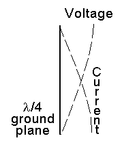
We know that voltage and current along a wire are 90°out of phase with each other. In a wire that is a multiple or fraction of a wavelength, at any point this also applies. This in effect gives a sinusoidal waveform in that wire. Where the voltage peaks the current is zero and where the voltage is zero, the current will peak. Hence a sine wave.
If the wire is resonant at a full wave then the full sine wave exists along it. If it is a half wave resonant wire you will get a half a sine wave effect. The diagram below shows the voltage and current levels in a 1/4 wave resonant wire such as in a 1/4λ ground plane aerial. See the voltage is at a peak when the current is lowest and the current is at a peak where the voltage is lowest.

The origin of some of the text on this page is from the RSGB with additions by the web master