

Technical Basics
Tuned circuits and resonance
2H1 Recall that a series or parallel circuit of a capacitor and inductor together forms a tuned circuit.
A tuned circuit is formed from a capacitor and inductor
![]() Students are not being able to recall this simple
series tuned circuits and understand what it is.
Students are not being able to recall this simple
series tuned circuits and understand what it is.
Inductors and capacitors can be used in circuits in two configurations to make :- Series tuned circuits and Parallel tuned circuit.
Series tuned circuit
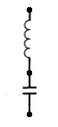
In this circuit the inductor and the capacitor are linked in series with each other making a series tuned circuit
Tuned circuits only work where the signal is an AC one....either Audio or Radio frequency.
The most notable feature of a series tuned circuit is that it presents a very low impedance across its' terminal at resonance. Quite the opposite of the parallel tuned circuit.
The effectiveness of a tuned circuit is given the term " Q "....so the better the goodness of a tuned circuit the higher the Q. Series tuned circuits have many uses e.g they can control the frequency of a VFO or control the selectivity of a receiver to name just two. A series tuned circuit will pass AC to a greater or lesser degree depending on the frequency...however it will never pass DC because the capacitor will not allow the flow of DC current!
Parallel tuned circuit
![]() Students are not being able to recall this simple
parallel tuned circuits and understand what it is.
Students are not being able to recall this simple
parallel tuned circuits and understand what it is.
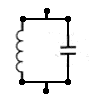
In this circuit the inductor and capacitor are linked in parallel with each other making a parallel tuned circuit.
The most notable feature of a parallel tuned circuit is that it presents a very high impedance across its' terminals at resonance. Therefore it will not pass AC at the resonant frequency...but it will be a dead short to DC across its' terminals....this is because the coil has no resistance to the flow of DC. (The parallel tuned circuit will pass AC to a greater or lesser degree depending of course on the frequency!)
The effectiveness of a tuned circuit is given the term " Q " So the better the goodness of a tuned circuit the higher the Q of the tuned circuit. A tuned circuit with a Q of 120 to 150 is a very good one and difficult to achieve in practice. The inductance of the coil versus the capacity of the capacitor affect the tuned circuit performance. Parallel tuned circuits have many uses e.g they can control the frequency of a VFO or control the selectivity of a receiver to name just two.
Differing values of inductance can all be made to resonate at the same frequency just by varying the amount of capacity used either in parallel or series. The ratio of the inductance of the coil versus the capacity of the capacitor affects the tuned circuit performance...the Q.
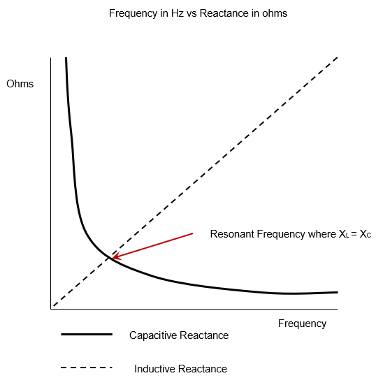
Recall, using graphical methods, that at resonance the reactance of the capacitance will equal the reactance of the inductance, XC = XL.
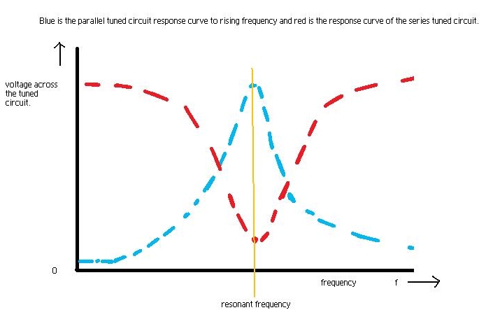
The diagram shows that a parallel tuned circuit (blue) has a voltage that peaks at resonance showing an increase in impedance and a series tuned circuit (red) the voltage lowers - impedance is low. At resonance the two reactances will be the same so XL = XC.
2H2 Recall that, at their resonant frequencies, series tuned circuits present a low impedance, whereas parallel tuned circuits present a high impedance.
Whilst tuned circuits are often in oscillators you need to know that:-
a parallel tuned circuit can be used to reject current at its resonant frequency such as when it is used as an antenna trap. It has high impedance.
NB the current is AC ( as is the current in RF ) as it does not work with DC.
a series tuned circuit can be used to accept current at its resonant frequency. It has low impedance.
NB the current is AC ( as is the current in RF ) as it does not work with DC.
SO - Be aware that the circuits have many uses in radio frequency technology - in relation to AC / RF circuits as the principle does not apply to Direct Current as DC has no frequency of oscillation (it is constant all the time).
Identify the response curves of impedance vs frequency for series and parallel resonant circuits.
For this part of the syllabus all you need to remember is the shape of the resonance curves for series and parallel tuned circuits.
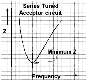
Series tuned circuit
A series tuned circuit has its lowest impedance (Z) at resonance hence the term acceptor circuit.
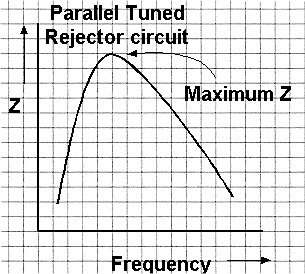
Parallel tuned circuit
A parallel tuned circuit has its highest impedance (Z) at resonance hence the term rejector circuit. This high impedance at resonance is used for instance for "traps" in aerials to electrically shorten a dipole aerial making it operational in two bands.
2H3 Recall that the energy stored in the capacitor and inductor in a tuned circuit can transfer from one to the other at a particular frequency, known as the resonant frequency.
Earlier it was explained that a capacitor could store electric energy, and it stores it in the plates of the capacitor in the form of a charge. Also it was explained that an inductor can store energy in the form of a magnetic field generated by a previous flow of current.
The diagram below shows a capacitor that can be switched across an inductor.
![]() How it
all works !
How it
all works !
If a charge were built up on the capacitor by another part of the circuit then when the switch is closed the potential difference due to the charge on the capacitor would cause electrons to flow through the inductor. As the current (electrons) flow from the capacitor it will slowly looses it charge, or as it is called "discharges", whilst at the same time a magnetic field builds up around the inductor.
When the capacitor is fully discharged the current can no longer flow but then the magnetic field around the inductor starts to collapse and induces a potential difference, opposite to that was originally on the capacitor which causes a current to flow which recharges the capacitor.
Thus once the magnetic field around the inductor has completely collapsed (reduced to nothing) the potential difference is zero - no current flows and the capacitor is then able to start to discharge again but this time in the other direction, until it is discharged at which point the inductor's magnetic field collapses again and the induced potential difference causes the current to flow to recharge the capacitor to the state it was when the switch was first closed.
In theory the charge and discharge could continue forever (so long as the switch remains closed) but nothing is so perfect as there are losses in the circuit. Thus the charge and discharge will slowly diminish and eventually stop.
Recall how the resonant frequency depends on the value of
capacitance and inductance.
Note that candidates must know that increasing L or C
reduces the resonant frequency and vice-versa. Knowledge of
the resonant frequency formula is not required.
The rate at which the charging and discharge cycle takes is determined by the value of capacitor its capacitance and the value of the inductor its inductance. The larger each of these values is the slower the charge and discharge cycle occurs.
The frequency or rate at which the charge and discharge cycle take place is called the resonant frequency and then the tuned circuit is described as being resonant. Change the L or C and the resonant frequency will change.
2H4 Recall that selectivity of a tuned
circuit is the ratio of the bandwidth of the circuit (that
is the range of frequencies the circuit will accept) to the
resonant frequency.
The concept of Q is not easy to understand, but do not be put off by the name "Q" it is not a 007 special agent.
Let's liken Q to something that you can understand. If you deposited £100 in a bank and a week later returned to with draw the money and received £200 you would say that the bank was rather good and that your money had been magnified by 2
Now if went you went back to the bank you received £1000 you would first think that the bank was fantastic and then may be that your £100 had been magnified by 10 or had a magnification factor of 10
magnification factor is also known as Q so we could say that the Q factor of the bank was 10.
So let's go back into the world of amateur radio and consider Q and resonance.
The half power point of bandwidth is where the level of the response has
fallen to ![]() (0.707
or 70.7%) of the maximum response or the -3dB level.
(0.707
or 70.7%) of the maximum response or the -3dB level.
The shape factor is the ratio of the bandwidth at -60dB and -6dB
Assuming that we loosely couple a signal generator into the inductor of a parallel LC circuit and measure the voltage across with an RF voltmeter
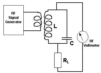
Now let us sweep the input frequency and draw graph of the resulting voltage changes.
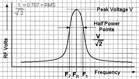
![]() is
the resonant frequency giving a peak voltage,
is
the resonant frequency giving a peak voltage, ![]() .
.
The points either side are generally accepted as limits of usable
frequency - This range ![]() to
to ![]() is the bandwidth [e.g.. 12kHz for speech] for
a parallel LC circuit. ( That could be the load in a valve power RF amplifier. )
is the bandwidth [e.g.. 12kHz for speech] for
a parallel LC circuit. ( That could be the load in a valve power RF amplifier. )
The equation for Q given the resonant frequency and the half power points on the resonance curve.
The circuit above shows a parallel tuned circuit with an RF voltmeter, such as is used in a common form of Q meter. Q meters give a measure of "Goodness" of a component or circuit. From the above resonance chart we have the equation for the resonant frequency and half power points which is :-
![]() =
= ![]()
which is also the Bandwidth F1 & F2 compared to the resonant frequency FR = SELECTIVITY
Calculating Q of a response curve
If we had a response curve where the centre frequency FR was 10MHz and a band width of 200kHz (F1 - F2) what will be the "Q" of the circuit ?
![]() =
=
![]() =
=

![]() =
=
![]()
Recall that the Q factor of a tuned circuit is an indication
of the selectivity of the tuned circuit.
In the diagram the range between F1 and F2, the bandwidth, shows the Q or "goodness" that is the amount of selectivity of the tuned circuit. This selectivity could be 300 Hz for a CW signal, or 12.5 KHz for an FM signal. Outside of this range lower and higher frequencies are said to be "cut off".
The cut off frequency of a filter is determined as the frequency where the amplitude of the signal is 3dB down from the maximum of the Pass Band, (ie half) that of the pass band or it can be said that the Fcut off is the frequency where the response is 3dB down. This amount 3B down is equivalent to a loss of a half. You will learn more about dB (decibels) later in the course.
2H5 Identify the circuits of simple low pass, high pass, band pass and band stop (notch) filters and their response curves.
Recall, using graphical methods, the concept of the cut-off
frequency.
The following are the diagrams of the filters for you to see in the Intermediate course.
Response curves, Filters and their components, and Remember the differences!
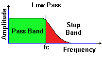
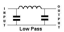
Passes all frequencies below the cut off frequency.
The capacitor's symbols could be thought of as bricks in a wall that cannot alter and thus stay low hence you can remember the configuration of the low pass filter.
The PASS BAND are the frequencies which the filter will PASS. Fc is the CUT OFF frequency
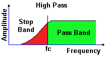
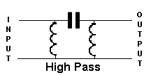
Passes all frequencies above the cut off frequency
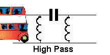
This is not intended to indicate what frequencies are passed but only the fact that the inductor looks like springs, and a bus is high, hence this may help you to remember the configuration of the HIGH pass filter
The PASS BAND are the frequencies which the filter will PASS. Fc is the CUT OFF frequency
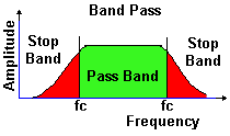
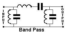
Band pass filter passes all frequencies in the pass band
Fc are the CUT OFF frequencies
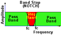
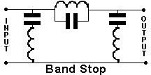
Band Stop filter passes all frequencies outside the stop band. Depending upon the design of the filter the "notch" could be very sharp and narrow or as shown broader and thus wider.
The PASS BAND are the frequencies which the filter will PASS. Fc are the CUT OFF frequencies
Whilst the input and outputs have been marked on some of the filters, with these simple filters the connection can be reversed but in complex filters this is not always the case.
The origin of some of the text on this page is from the RSGB with additions by the web master