

Section 4
Feeders and Antenna
Antenna concepts
4C1 Recall that the purpose of an antenna is to convert electrical signals into radio waves (and vice-versa) and that these are polarised according to the orientation of the antenna, e.g. a horizontally oriented antenna will radiate horizontally polarised waves
Purpose of the antenna
The electrical signal, or electrical energy that comes from the 'RADIO TRANSMITTER' to the AERIAL via the coaxial feeder is actually a TUNED RADIO FREQUENCY Signal
In order for this signal to leave the coaxial feeder and radiate into the air, we need what is called an AERIAL.
This Aerial needs to be made for the band of operation, tuned to the frequency that the transmitter is operating on else the amount of radiated signal will be much reduced and the other station may not even hear you.
With a properly tuned aerial on the end of the coax, the electrical energy, or to use the correct term, the Radio Frequency Signal (RF signal), will now radiate into the atmosphere (and at HF into the ionosphere and be reflected back but more about that in the section on Propagation) so that the person that you want to talking to can hear you.
The same rule applies with the received signal, in that the correctly tuned aerial must be used to receive a signal properly. Normally in Amateur Radio use, we use the same aerial for receiving as we do for transmitting on for that same given frequency.
Polarisation
The polarization of the antenna is dependent upon how the radiating elements are orientated. Vertically gives vertical polarization horizontally gives horizontal polarization.
To obtain the best reception from a vertically polarised signal transmitted signal, your antenna need to also be vertically polarised.
To obtain the best reception from a horizontally polarised signal transmitted signal, your antenna need to also be horizontally polarised.
FM transmissions
In amateur radio it is usual for FM transmissions to be from a vertically polarised antenna such as the 1/4 wave 5/8 wave.
SSB Transmissions
In amateur radio it is usual for SSB transmission to be usually from horizontally polarised antennas.
Polarization is particularly important at VHF and UHF because if cross polarization exists with one station using an antenna vertically polarised and the other station using and an antenna horizontally polarised it will result in poor or even no reception where as had both stations been using the same polarisation of antennas reception would have been sufficient for communication.
At HF the importance of the polarisation of the antennas is much less as the radio signals will change polarization during their travel from the distant transmitting station to your reception and similarly on the reverse route.
4C2 Understand the concept of an antenna radiation pattern.
Identify the polar diagrams for the half wave dipole and Yagi antennas.
Polar diagrams are a graphic representation of the radiation pattern of an antenna. With the dipole located at the centre and two lobs each side of the antenna.

With the Yagi a main lobe leads out wards from the driven element (the small but broader line) outwards towards the smaller directors. Some times smaller lobs exist off the side of the antenna called side lobes.

Identify the directions of maximum and minimum radiation.
The maximum radiation is into the large lobe on both the dipole and the yagi with minimum is off the ends of the driven element thus in both cases the max radiation is at right angles to the driven element.
Understand that half-wave dipoles (mounted vertically), 1/4 (quarter wavelength) ground planes and 5/8 wave antennas are omni-directional.
The 1/4 wave GROUND PLANE AERIAL is always used as a vertical and as such has an omni-directional wave form.
This picture is a representation of the 1/4 wave ground plane antenna looking like a round dough nut as the radiating wave form and the antenna is pushed up through the middle.
This radiating pattern all round the antenna is what is meant by OMNI-DIRECTIONAL.
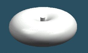
THIS PICTURE IS A REPRESENTATION
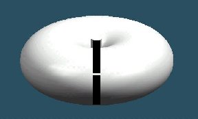
Now if we take a slice though the wave form you will see the radiating element.

The 5/8 WAVE AERIAL has 'similar' properties to the 1/4 Wave Ground Plane Aerial. The only difference's being, the 5/8 Wave Aerial is BIGGER, and has a slight 'GAIN' of signal to its output compared to a 1/2 Wave dipole, or a 1/4 Wave Ground Plane but is also OMNI-DIRECTIONAL.
If a half wave dipole is also mounted vertically instead of the usual configuration of horizontally it too will exhibit omni-directional radiation.
The picture is a representation of a dipole mounted vertically with the same omni-directional radiation.
Note: only dipole and Yagi antennas will be examined for radiation pattern
4C3
Understand that antenna gain is due to its ability to focus radiation
in a particular direction.
The YAGI focuses the RF into a beam sending it in a particular direction, in which the beam is pointing, so avoiding radiating the transmissions in directions other than towards the direction required to maximize the received signal for the station being worked.
A YAGI BEAM Aerial is a DIRECTIONAL Aerial, with higher gain than the aerials previously discussed.. This is achieved by the REFLECTOR on the back of the aerial, which forces the signal forward to the DIRECTORS.
The directors focus the RF Signal energy forward like the light beam of a car's headlight or a torch beam. A yagi (beam) aerial can be used vertically polarised or horizontally polarised. Due to the large physically size of a yagi one designed for HF is normally horizontally polarised.
Recall that a Yagi antenna typically has a higher gain because of its improved focussing ability.
The yagi antenna typically has a greater/higher gain because of the Yagi improving the focussing ability of the antenna.
Recall the gain of an antenna is normally expressed relative to a half-wave dipole and measured in dB (Higher dB value is a higher gain).
As a half wave dipole has effectively zero gain then the dipole is the antenna against which other antennas are judged. the gain is measured in dB (the Higher the dB value is a higher gain.)
Recall
that the directional power is expressed as Effective Radiated Power
(ERP) and that the apparent power increase is known as gain.
Directional power is expressed as EFFECTED RADIATED POWER (ERP) and that apparent power increase is know as GAIN
Recall that ERP is calculated by multiplying the power applied to the antenna feed point by the gain of the antenna.
ERP = EFFECTIVE RADIATED POWER
Most manufacturers inform you of the gain of their antenna by using the scientific notation dB which stands for decibels. Whilst this may appear more complex you will be meeting it again in the Intermediate and Advanced courses.
Calculate ERP given antenna input power and antenna gain. Note: dB conversion table (3, 6 & 10) will be provided
Power leaves your transceiver and travels up to the antenna. If you are using an antenna which has what is called "GAIN" then effectively you will be getting more out of the antenna than you are putting in. This is only possible because of the antenna construction.
So what is this EFFECTIVE power. As the power is being radiated we called it EFFECTIVE RADIATED POWER (erp) and this is given by this formula :-
ERP = power fed to antenna from the rig x antenna gain
using linear units and no allowance for feeder loss.
So if you have a transceiver which has power output of 10 watts and the antenna has a gain of 10 the ERP = 10 watts (output) x 10 (gain) = 100 Watts EFFECTIVE RADIATED POWER
BUT consider this .....
This means that if the licence conditions state that the maximum ERP is 10 Watts, and the radio in use only gives output 1 watt of RF Power, then an aerial with a 10 times gain will produce the highest legal power for that frequency. Also, if for the same frequency, the radio in use has a maximum RF Power output of 5 watts, and the aerial in use has a gain of 2 times, then the ERP will be 10 Watts.
You will need to be able to manipulate the equation ERP = power fed to antenna from the rig x antenna gain just as you did V = I x R and P = V x I
So construct another magic triangle for your self. If you have problems with it chat to your club's tutor.
4C4 Recall that antenna gain can also be expressed relative to a theoretical antenna that radiates equally in all directions and this is shown as EIRP, Effective Isotropic Radiated Power.
Here is a new concept. If it were possible to have an antenna radiate in all directions this is called EIRP or EFFECTIVE ISOTROPIC RADIATED POWER, that is a fact you need to just learn!!
Recall that 10W EIRP is equivalent to 6.1W ERP
Now you have the notion in your head you have to learn that 10W EIRP is equivalent to 6.1W ERP
4C5 Recall that VHF and UHF signals will normally be received most effectively when the transmitter and the receiver have the same antenna polarisation and that this is less important at HF because the polarisation may change during ionospheric reflection
You need to be able to recall from understanding that if you are using VHF or UHF frequencies into Yagis then the polarisation of the transmitting and receiving antenna must be the same for best recepption of the transmitted signal is not then the signal will be very much reduced in signal strength.
However when dealing with HF signal the polarisation is much less importance because as HF signal travel and meet the ionosphere their polarisation may be changed.
4C6 Recall that the connection point of the feeder to the antenna is called the feed point.
You need to understand the term FEED POINT as this is the connection point on an antenna for the feeder.
Recall that at the design frequency the feed point has an impedance that should match the impedance of the feeder and the transmitter.
When an antenna is designed consideration is given to ensure that the impedance of the feed point is the same as that of the transmitter - a fact you need to learn.
Recall that the feed point impedance of an antenna is related to the dimensions of the antenna and the wavelength of the applied signal.
A further design point for an antenna is that the feed point impedance is related to the dimensions of the antenna and the wavelength (frequency) of the applied (transmitted) signal.
Recall that if the feed point impedance of the antenna does not match that of the feeder, energy will be reflected back down the feeder; the proportion reflected depending upon the degree of mismatch
Lastly in the topic is the the feed point impedance and that of the feeder itself must be the same else there is a mismatch and energy which would normally reach the antenna is reflected back down the feeder to the transmitted, the amount that is reflected is dependent upon the amount of mismatch
The origin of some of the text on this page is from the RSGB with additions by the web master