

Section 4
Feeders and Antenna
Types of antenna
4D1 Identify the half-wave dipole, 1/4 (quarter wavelength) ground plane, Yagi, end fed wire and 5/8 (five eighths wavelength) antennas.
Aerials come in many types and shapes. At this stage, we will only be dealing with five types of aerial, these are:-
- the 1/2 wave DIPOLE aerial
- the 1/4 Wave GROUND PLANE Aerial, sometimes the GROUND PLANES are called RADIALS
- the Yagi aerial
- the End fed wire or LONG WIRE Aerial
- the 5/8 WAVE VERTICAL Aerial. This also has Ground Planes which are also sometimes called Radials.
Each
of these aerials can be used on most bands and operate on the same basic
principles, the deciding factors are dependent :-
on the physical size of the aerial,
the amount of space available to use the aerial.
The size of any given aerial is also governed by the FREQUENCY, or
WAVELENGTH on which the aerial is designed to operate on. The lower the
frequency, the longer the Wavelength, and so, the longer or bigger the
physical size of the aerial. Conversely, the higher the frequency, the
smaller the physical size or length.
Below are diagrams of the dipole, 1/4 wave ground plane, yagi, end-fed
wire and 5/8 wave antenna. None of the diagrams are to scale as the size
is dependent upon frequency of operation. In any antenna its size is
frequency dependent.
The half wave dipole is the most basic of all antennas and is the antenna against which all others can be judged. The dipole can be used vertically or horizontally. The diagram show the antenna in the horizontal position and would be said to be horizontally polarised.
A DIPOLE aerial can be mounted Vertically or Horizontally. Normally for VHF & UHF working, a dipole is used in Vertical Polarisation. When a Dipole aerial is used vertically polarised, it is OMNI DIRECTIONAL. This means that it transmits in all directions around its element. However if a DIPOLE Aerial is used Horizontally Polarised, it only radiates as a outwards from the elements and no signal is from the end, and thus can have some directional element in its use.
Note:
that the radiating vertical element and the horizontal ground planes are
all 1/4 wave long. The Ground plane antenna is always used vertically.
The yagi is said to have gain as it focuses the radio waves into a generally single direction and is not therefore wasting power radiated in directions where it is not required. The Yagi can be used vertically or horizontally. The diagram shows the antenna in the vertical position.
The end fed wire is simply a random length of wire attached to the centre of a coax feeder or more usually linked directly onto the rear of a suitable ATU that can take single wire. This is a poor antenna as it is not tuned to any particular frequency and thus generally performs badly relative to a dipole.
 What is a long wire
? It is usually a random length of wire which is often
connected directly to the terminal of an ATU which can accept
long wire as well as coax feed and ladder wire fed antennas.
The likely minimum length of the wire will be 80 feet but is
often much longer.
What is a long wire
? It is usually a random length of wire which is often
connected directly to the terminal of an ATU which can accept
long wire as well as coax feed and ladder wire fed antennas.
The likely minimum length of the wire will be 80 feet but is
often much longer.
Note :- the 5/8 wave has a slightly better gain over the 1/4 wave antenna shown above. Also used vertically, it differs from the 1/4 wave in that there is a loading coil at the base of the antenna.
Understand that the sizes of HF and VHF antennas are different because they are related to wavelength, though they operate on the same basic principles.
Above you saw the drawing of the dipole where as below is the symbol you could have in the written assessment

This is where the link between the size of the aerial and it wavelength is established. The overall length of both the legs of the 1/2 wave dipole ( /2 dipole) measure about the same length as the conversion of the frequency into the wavelength/2 with the answer given in metres. As a generality 14MHz has a wavelength of 20m. Thus the overall length of a 14 MHz half wave dipole is 10 metres so each leg would be about 5 metres.
However a dipole for say 2m 144MHz is about 1/4m for each leg or about 1/2m overall.
So you can see that HF antennas are much larger in overall length than a VHF but the principles of thier size is the same.
Understand that the 1/2 (half wavelength) dipole has a physical length approximately equal to a half wavelength of the correct signal
It is worth repeating here that the ?/2 (half wavelength) dipole has a physical length approximately equal to a half wavelength of the frequency of the signal being transmitted.
Finally, and not mentioned in the syllabus, but we think you need to know there is the Dummy Load Antenna.
A "dummy load" is a screened resistor connected instead of an antenna to allow the transmitter to be put into transmit (operated) without radiating a signal or at most a very small signal.
A DUMMY LOAD is an artificial aerial, used for test purposes.
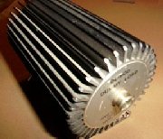
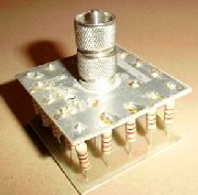
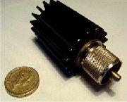
The dummy loads shown above represent a range - 100watt down to 5 watts.
The Dummy Load MUST be made from CARBON RESISTOR(s) with short connecting wires.
As can be seen from tone of the images the dummy load is several carbon resistors in parallel making up 50 OHMS, or a single large CARBON RESISTOR built into a heat sink with the correct connectors on it so that the Dummy Load can be connected to the radio TRANSMITTER / RECEIVER or ATU / SWR Meter for test purpose's without radiating a signal. Tests such as, looking for power loss in feeder, or to test for faults in the feeder or the aerial can be done by putting the Dummy load at the point where the antenna would attach.
The reason that a 50 ohm CARBON resistor is used, is because 50 ohms is the correct impedance value of the aerial system into which the transceiver transmits. The Dummy Load MUST be made from CARBON RESISTOR.
 A WIRE WOUND resistor is
effectively an inductor ( a coil of wire ) and because the dummy load
must not have any inductive properties the wire wound resistor,
although of wattage capability and easier to obtain cannot be used.
Inductive properties in a dummy load could lead to problems such as
radiating a signal.
A WIRE WOUND resistor is
effectively an inductor ( a coil of wire ) and because the dummy load
must not have any inductive properties the wire wound resistor,
although of wattage capability and easier to obtain cannot be used.
Inductive properties in a dummy load could lead to problems such as
radiating a signal.
The origin of some of the text on this page is from the RSGB with additions by the web master