

Transmitters and Receivers
Transmitter concepts
3A2 Recall the meaning of depth of
modulation for amplitude modulation.
Recall the meanings of wide band and narrow band frequency modulation.
Recall the meaning of the term Peak Deviation.
There is a lot of what is believed to be "hidden" topics within this section so let's first start with The meaning of the term peak deviation.
When dealing with FM you will come across the term Peak Deviation which means the MAXIMUM amount by which the frequency of the signal may deviate from the carrier frequency.
Deviation is the frequency change from the carrier frequency both above the carrier frequency and below.
The amount of the deviation is proportional to the amplitude of the applied signal and NOT the frequency of the applied signal. Thus the louder you speak into the microphone the greater the voltage that will be applied to the stage and the greater the deviation.
Greater the applied voltage the greater the deviation
Thus a signal of 3mV at 1kHz will create greater deviation than a signal of 1mV at 3kHz
Now let us understand meaning of "Narrow Band" and "Wide Band" modulation for frequency modulation.
The peak deviation is used to assess the Modulation Index.
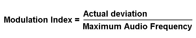
This is also know by the following :-
Deviation Ratio = Actual Deviation / Maximum deviation
In the world of broadcast radio the Modulation Index is 75kHz divided by 15kHz = 5 and being greater than one is described as Wide Band FM or WBFM.
In amateur radio in the 2m band with 12.5kHz channel spacing the peak deviation is usually 2.5kHz with a maximum audio frequency of about 3kHz giving a Modulation Index of 0.83 and being 1 or less is termed Narrow Band FM or NBFM.
Let's us explore the meaning of depth of modulation for amplitude modulation.
First let us recall the diagram of wave forms from your Foundation Licence course.
This should need no explanation but let's remind you that the audio signal is that into say the microphone, the carrier is the carrier whether it is AM of FM, the modulated carrier as shown is the AM wave form.
Now the wave forms have been changed a little as we are to explain Depth of modulation. Modulation index can be defined as the measure of extent of amplitude variation about an un-modulated carrier.
M = RMS value of modulating signal / RMS value of unmodulated signal. If expressed as a percentage it is the same as the depth of modulation.
Notice that at the start of the audio wave for the audio is zero and there is only carrier on the AM signal. Then notice how the audio wave form increases the amplitude of the carrier when the signal is positive and reduces the carrier when the signal is negative.
Thus the audio signal is carried as an exact image of itself on the AM signal, assuming no distortion which there must not be else the received audio would also be distorted.
The Depth of Modulation
It is typically the modulation index expressed as a percentage.
Thus a modulation index of 0.5 would be expressed as a modulation depth of 50%, etc. Depth of modulation is the peaks and troughs of a modulated carrier wave. Thus in the example shown M=A/B (0ther information sources may show this differently). It is said that the amplitude of the carrier wave is doubled because the variation between the peak and the trough of modulated is twice that of the carrier amplitude.
Looking at value of A and B shows that the carrier wave is more or less 100% modulated, as half is amplitude above the carrier and half below .5 + .5 = 1 or 100% Increasing modulation further still would over-modulate the carrier causing break up in the signal and distortion in the resultant audio.
3A3 Understand that single sideband (SSB) is a
form of amplitude modulation where one sideband and the
carrier have been removed from the transmitted signal.
Understand that SSB is more efficient than AM or FM
because power is not used to transmit the carrier and the
other sideband.
Understand that a second advantage is that the transmitted signal takes up only half the bandwidth, e.g. 3kHz not 6kHz.
SSB is where one sideband and the carrier have been removed from the transmitted signal. See the similarity in the diagrams below which are derived from the AM signal diagram.

SSB makes more efficient use of the power from your transmitter as power is not used to transmit the carrier and the other sideband.
Because the signal is without the carrier and one side band the transmitted signal takes up only half the bandwidth, e.g. 3 kHz not 6 kHz.
![]() So what happens to the
carrier and other side band? They are both suppressed by the
rig's filtering and then put back in by the receiver hearing
the signals.
So what happens to the
carrier and other side band? They are both suppressed by the
rig's filtering and then put back in by the receiver hearing
the signals.
In passing you must understand that a CW signal occupies the least bandwidth as there is no modulated audio signal and that FM occupies the most bandwidth due to the nature of the signal.
Recall that :
⦁ AM uses less bandwidth than FM
⦁ SSB uses less bandwidth than AM
⦁ CW uses less bandwidth than SSB.
⦁ Digital modes may use less or more bandwidth than any of the
above.
Transmitter architecture
3B1 Understand the block diagrams of CW, AM, SSB and FM transmitters.
![]() Students are not
being able to recall these simple block diagrams and understand what they
are. Please take time and learn about their differences.
Students are not
being able to recall these simple block diagrams and understand what they
are. Please take time and learn about their differences.
In the CW Tx the morse key is connected into the "keying stage" indicating that the RF oscillator remains undisturbed whilst the keying is carried out.

With the AM Tx a modulator is required after the RF oscillator to mix the oscillator signal with the audio signal.
In the SSB Tx the signal is applied to a balanced modulator (also called a balanced mixer) and there is a sideband filter to remove the unwanted sideband.
The FM Tx is the only one where the audio signal is mixed directly with the RF oscillator as it says in the name Frequency Modulation. It is the frequency that is changed and to do this the RF oscillator must be acted upon.
Note:- In ALL cases the Power amplifier stage has a low pass filter following and prior to the antenna connection to reduce unwanted signals from radiating.
Oscillators
3C1 Recall and understand the relative advantages and disadvantages of a crystal oscillator and a VFO.
There are two basic types of RF oscillator, the crystal controlled oscillator and the Variable Frequency Oscillator (VFO). The two oscillators have different characteristics which determine which is the best for a particular application.
The key characteristics are:
Crystal Controlled Oscillator
-
Provides very good frequency stability in that is can be considered as a fixed frequency signal that is accurate, stable, and can be used as a reference.
-
Frequency of operation is dependent on the design frequency of the Crystal.
Variable Frequency Oscillator (VFO)
-
Provides a signal that is tunable over a range of frequencies
-
Difficult to get an accurate and stable RF signal as the frequency can drift.
-
A tuned circuit determines frequency of operation.
-
By varying the inductance or, more usually, the capacitance in the tuned circuit we can vary the frequency of operation.
Recall that the resonant frequency of the tuned circuit in
a VFO determines the frequency of oscillation.
In the section on Inductor the term "tuned circuit" was used for for the first time.
It is the resonant frequency of the tuned circuit which determines the frequency of the oscillation.
3C2 Recall that the frequency stability of an oscillator can be improved by rigid mechanical construction, screening the oscillator enclosure, a regulated DC supply and a buffer amplifier immediately after the oscillator circuit.
Understand that a lack of stability (drift) may result in operation outside the amateur bands.
Once the transmitter is set to a frequency an oscillator continues to output a constant frequency. We refer to the ability to remain on the set frequency as stability.
The frequency of the oscillator can change due to:-
-
a variation in the supply voltage or
-
small variations in the inductance or capacitance caused by vibration or
-
variation in temperature.
Even crystal oscillators can be affected by such variations although they are generally better in this respected than tuned circuit oscillators.
Therefore, good RF oscillator design demands:
Rigid construction - To prevent changes in frequency mechanical movement of inductors and capacitors due to vibration.
A regulated (stabilised) DC supply to the oscillator - To minimise changes in frequency due to changes in supply voltage.
Screening - To limit the effects of stray capacitance and to limit leakage of unwanted RF from or into the RF oscillator and to limit the effect of changes in temperature due to air movements.
Recall that most modern oscillators are digital synthesisers, which are very stable and are based on a crystal reference.
In modern equipment, many of the limitations in the two basic types of oscillators (crystal and variable) can be generally overcome by the use of the modern frequency synthesiser.
There are a various designs of frequency synthesiser which use a master crystal oscillator as a reference for a variable frequency oscillator. The resultant output signal is therefore, accurate, stable, and variable.
3C3 Recall that digital signals can be used to generate audio and RF signals by Direct Digital Synthesis (DDS).
We saw earlier in our block diagram of an SDR receiver that there is a part called DDS or Direct Digital Synthesis. DDS converts digital signals in its electronics to produce signals in the range of audio through to RF levels in the form of sine waves.
Recall the meaning of DDS.
Recall that a Direct Digital Synthesiser generates audio and RF signals from pre-set digital values held in a memory, or Lookup Table.
The DDS uses its digital to analogue converter (DAC) part to produce the required voltages from a "look-up table" in its memory to create the output sine wave. E.G. in a receiver this could be audio level sine waves which then go on to be amplified for the sound we hear through a speaker. The DDS/DAC is normally followed by filter to clear up spurii created by the "chopping" of the incoming signal.
Note that the DDS IC can also work in reverse in a transmitter circuit to produce Digital signals from the audio in from the microphone which become RF signal levels.
The origin of some of the text on this page is from the RSGB with additions by the web master