

Transmitters and Receivers
SDR transmitters and receivers
3M1 Recall that SDR software uses a mathematical function called a Fourier transform which sifts the composite signal into its constituent independent frequencies for processing.
From the Foundation course we learned an SDR (Software Defined Radio) receiver receives all the electromagnetic RF from the antenna and converts those analogue signals to a digital format for processing in Software. The complex mathematical function is called Fourier Transform. The full mathematics knowledge is not required for this course.
The way the Fourier transform works is by using the digitised slices that were taken from the ADC output, which is a complex spectrum of signals, and converting them into its constituent signals across the bandwidth e.g. carrier signals for C.W. or A.M.
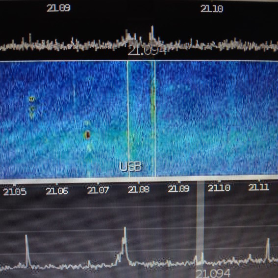
This photo shows the graphical output from the ADC at the top over a narrow received spectrum. Note that it is still a complex mixture of signals. The graph at the bottom of this photo shows a moment in time spectrum after the Fourier Transform has cleaned it up. The two little blips in the white bar are from a weak RTTY ( Radio Teletype ) signal that has 2 audio outputs spaced 170Hz apart.
Recall that this can also be used to provide a spectrum or waterfall display.
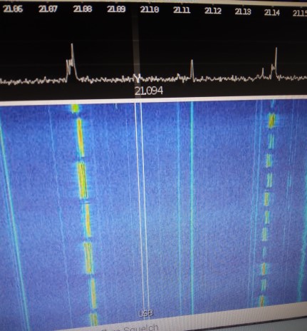
The software in the DSP can be used along with the graphical output circuitry to provide a spectrum ( top of photo ) or a waterfall display ( the blue area at the lower part of the photo). The spectrum display in these type of graphics is usually moving downward and hence gives a waterfall effect. You can see the very strong RTTY signal in yellow in the blue area which is collected over a period of time. These bright yellow parts are made up of two vertical bars that are 170Hz apart representing an RTTY signal. The spectrum and the waterfall are very useful for us to find stations in a spectrum bandwidth and helps us tune onto them.
Recall that digital filters can be much more selective than analogue filters.
Digital filters are very selective ranging from very fine, like here for 170 Hz, to several KHz in signal width, and many other values in between.
3M2 Recall the meaning of the time domain and the frequency domain.
Understand how signals in the time domain may also be viewed in the frequency domain.
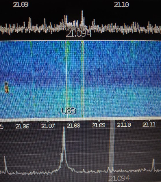
The photo above shows at the top section the spectrum of signals in a frequency band and is representative of a noisy time domain with a weak signal almost lost,but after the Fourier transform has done its job the result is shown in the bottom part where the 2 signals are clear. They are in the white band near where it says 21.094. This is the frequency domain over a very narrow bandwidth ( in the white band area ).
Identify for some simple harmonic waves, the spectrum
obtained using the Fourier transform.
(Waves composed of one and two Harmonics will be
examined).
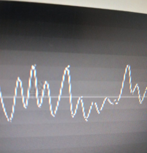
This photo shows a complex mix of a time domain signal which contain a primary signal and its harmonics. After Fourier transform we get them separated into 2 or more different signals.

This image graph represents the signal, now split up by Fourier transform into its frequency domain with Fundamental signal (1) and its second (2) and third (3) harmonics. The Fundamental (1) is the required frequency where (2) is twice the fundamental frequency and (3) is 3 times the fundamental frequency. The harmonics are then filtered out by the DSP so we just have the required signal (1) remaining.
3M3 Recall the different elements that make up the functions of an SDR (block diagram).
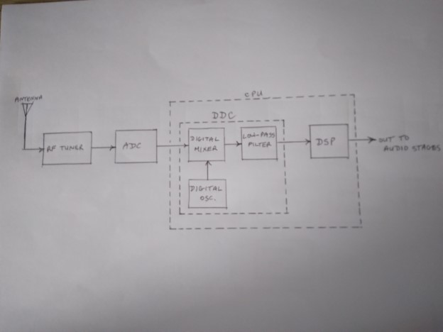
We have seen the SDR receiver before and here it is again for you to compare with the SDR transmitter below.
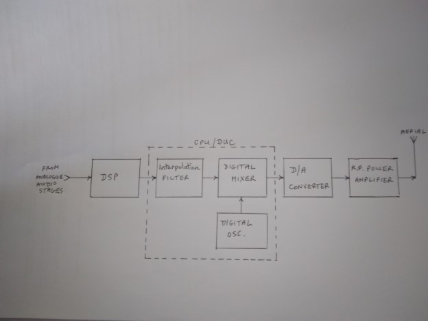
The receiver has a digital down-converter in the DSP (CPU) whereas the transmitter has a digital up-converter. In the transmitter the DSP converts the audio input into digital samples and produces the selected mode of operation and passes this to the digital mixer. It is then passed on to the digital to analogue converter to produce the radio frequency (RF) signals that are passed out to the aerial via an RF power amplifier.
You can see that the transmitter is almost the opposite in functions to the receiver. This means that in a transceiver a lot of the circuitry can be shared between the two. You may be shown a combined diagram in your exam and you may have to pick out a section that is blanked out out and name it.
The origin of some of the text on this page is from the RSGB with additions by the web master