

Technical Basics
Inductors
2D4 Understand the relative movement of a conductor in a magnetic field will induce a voltage across the ends of the conductor.
Moving a wire through a magnetic field such as one produced from a magnet will
cause a small amount of voltage to be produced in that wire, or induced. Hence the wire is
actually an inductor.
Similarly a magnetic field moving across a wire will induce
a voltage in that wire.
Recall that a current passing through a wire forms a magnetic field around the wire.
When a current passes through a wire it creates a magnetic field around the wire. You cannot see it but you can detect it by using a small magnetic compass. By bringing the compass near to the wire the compass needle will swing and align in sympathy with the lines of magnetic force. As the compass is moved from one end of the wire to the other the way the needle points will change, following the lines of magnetic force.
As soon as the current is stopped the magnetic field collapses - almost at once. The larger the electric current the greater the magnetic field.
Recall that an inductor is normally a coil formed of a number of turns of wire to concentrate the magnetic field and that inductance is measured in Henries.
Whilst a "conductor" is any piece of material that allows electrons to flow, such as a piece of wire, an "INDUCTOR" is normally a coil of a number of turns of wire which will concentrate the magnetic field. The wire is usually of large enough diameter so that it remains in the forms of the coil without collapsing if gently squeezed and is often in enamelled copper wire so that it is insulated from other components.
Recall that an inductor is able to store energy in its magnetic field.
Recall that the ability to store energy is known as inductance, which depends upon the number of turns of wire on the coil and its dimensions. This inductance is measured in Henries.
Recall that the ability to store energy is known as inductance, which depends upon the number of turns of wire
The inductor can store energy in the magnetic field caused by an electric current passing through it and this ability is called INDUCTANCE. The storage is not as prolonged as that as a battery and it is not the storage of an electrical charge but of energy.
2D5 Understand and apply the formulae for calculating the combined values of two or three inductors in series and in parallel.
The series formula is :-
When inductors are linked in series or in parallel then the total equivalent value is similar in calculation to that of resistors.
Thus total value of several inductors linked in series can be calculated from the formula:-
Can you deduce the other formula for inductors in parallel ??
Did you
work it out as 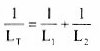 ................... just like
the resistor one !!!!
................... just like
the resistor one !!!!
2D6 Recall that the inductance of a coil increases with
increasing number of turns, increasing coil diameter and
decreasing spacing between turns.
The greater the number of turns the greater the inductance
Let's first look at that straight piece of wire mentioned above. The ability to store energy is dependent upon the number of turns so a piece of wire with one turn would not have the ability to store much energy at all.
So as the number of turns of wire in the coil increases so does it ability to store energy increase and hence the amount of inductance increases.
The greater the size of turns in the coil the greater the inductance
Further as the size of the coil's dimensions increase so does it ability to store energy also increases and hence the amount of inductance increases.
The closer together turns of the coil the greater the inductance
But there is also a third factor to consider. In addition to the greater the number of turns and the greater the size of the coil, the closer together the turns are to each other the greater is the inductance.
Understand the use of high permeability cores and slug tuning.
High permeability cores
So what is a high permeability core?
When you have an inductor wound on a former as part of a tuned circuit in order that the circuit can be "tuned" to a specific frequency the former is fitted with a high permeability core (also called a tuning slug). The core is threaded so that by the use of a non ferrous tool. When the core is wound into the coil the inductance is raised and when moved out the inductance lowers. This turning of the core moves it in or our of the former enables a tuned circuit to be brought to a point where it the coil (and capacitor) resonates. (You will learn more about resonant circuits later on in the course) Sometimes the slug might be partially out of the core. This operation is called slug tuning.
Coil with tuning slug
Should the inductance of the coil need to be further reduced this can be achieved by removal of the slug altogether or to achieve and even lower inductance can be achieved by the use of a "brass" slug.
The use of the core saves the need to change the size or number of turns on the coil.
Circuit diagrams of the inductor
It is necessary to know for the Intermediate Licence Examination that inductors have 3 different circuit diagram symbols.
 |
Standard (general) inductor. |
 |
Inductor with iron core. |
 |
a Transformer (two or more inductors with an iron core). |
The origin of some of the text on this page is from the RSGB with additions by the web master