

Technical Basics
AC theory
2E1 Understand that by repeatedly charging and discharging in alternate directions, a capacitor can pass alternating currents, but cannot pass a direct current.
Applying a DC voltage across the plates of a capacitor will charge the capacitor with electricity. The capacitor can hold a charge for a long time...indefinitely in the case of a perfect capacitor with no losses.
When the DC voltage is applied there is an in rush current that charges the capacitor. Once the capacitor is charged no further current will flow....in fact all current flow stops. A capacitor cannot pass DC once it is charged.
When an AC supply is applied to the plates of a capacitor there will be an in rush of current just as on DC, however once the supply changes polarity as the waveform reverses then the capacitor must discharge and then recharge in the opposite polarity. When the supply again changes polarity as the waveform reverts back the capacitor must again discharge and re-charge again in the opposite sense. So when you apply an AC waveform to a capacitor current is constantly charging and discharging the capacitor and flowing around the circuit.
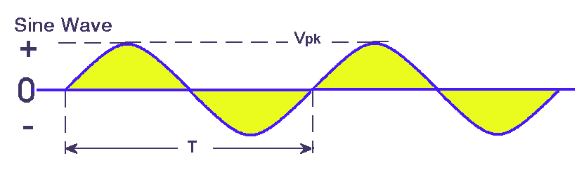
2E2 Understand the sinusoidal curve as a graphical representation of the rise and fall of an alternating current or voltage over time and that both the frequency and the amplitude must be specified.
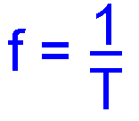
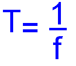
Recall that the time in seconds for one cycle is the Periodic Time (T) and the formula T=1/f and f=1/T where f is the frequency in Hz.
A sine wave is a pure wave and contains no harmonics. Any deviation from the pure sine wave curve is indicative of other products mixed in with the signal e.g. harmonics.
To fully describe a sine wave both the amplitude and the time for 1 cycle ( also called the periodic time ) or the number of cycles per second, the frequency in Hertz Hz must be specified.
However voltage quoted could be a peak to peak value or might be the RMS value.
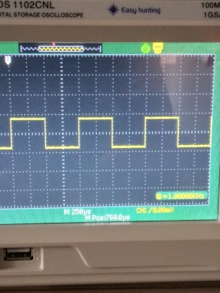
Recognise the graphical representation of a square wave.
You should know that a square is quite different to a sine wave and that square waves are used in the digital processing in Software Defined Radios. The change from peak to peak voltage is instantaneous, unlike a sine wave that is a gradual change. Here is a screen shot of an oscilloscope showing a square waveform:-
sinusoidal current. You should understand from earlier FLC and ILC topics that Mains electricity AC has a sinusoidal wave form as the voltage changes from zero to maximum positive and then zero and then maximum negative and then back to zero. You should also then know that if a current is flowing in an AC circuit then as the voltage changes so does the current according to Ohms Law V = I x R
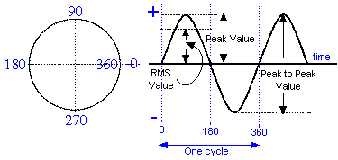
Let's take a look at the sine wave that you were first introduced to in the Foundation Licence course, but several new items are added in this course.
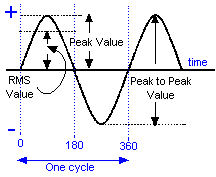
Up to now you have only been considering that part of the sine wave marked 0 to 360 (where it says one cycle in the drawing above) but you have understand that the sine wave does in fact does continue on indefinitely until the source of the sine wave is turned off.
Looking at the diagram you can see Peak Value. This is the maximum voltage of the sine wave. Knowledge of this is needed to understand RMS. RMS stands for ROOT MEAN SQUARE.
If you have a Direct Current from a DC source such as a Battery or Amateur Radio Power Supply and apply it to a circuit with a resistor in it then a current will flow and the resistor will warm up. The heating effect in the resistor will be according to the equation Power in watts = Volts x Current
P = V x I which you learned at FLC level.
Looking at the diagram ABOVE you can see words RMS Value. The RMS value is numerically equal to 0.707 of the Peak value as given by the equation below.
Taking this a bit further the RMS has the same heating effect as a Direct Current of the same numeric value. So if RMS value of the AC wave form is say 220V and the DC is 220V the heating effect will be exactly the same for the AC source and the DC source.
The square root of 2 is 1.414 then 1 divided by square root of 2 equals 0.707. Check that on your calculator even a simple one will give you the result!!

 which is
the same as Vrms = Vpeak x 0.707
which is
the same as Vrms = Vpeak x 0.707
Thus if the peak value was 240V AC the RMS would be 240 x 0.707 = 169. So if you had a DC voltage you would only need to have a voltage of 169 volts to give the same heating as 240V AC
In actual fact when we say mains voltage is 230V that is the RMS value - its peak is much higher !
Also observe that the measurement between one peak maximum positive and the peak maximum negative is called the Peak to Peak value.
Finally the horizontal axis through the centre is the time axis and is the + and - volts.
Recall that the time in seconds for one cycle is the Periodic Time (T) and the formula T=1/f and f= 1/T where f = frequency in Hertz and T = time interval in seconds.
The time taken for one complete cycle is known as the Periodic Time.
The relationship between Periodic Time (T) and Frequency ( f in Hz) can be expressed like so:
T = 1/f or transposing it to give f = 1/T where f is in Hertz.
It is worth pointing out that in earlier times the frequency was measured in Cycles per Second ...these days Hertz, abbreviated to Hz is now used.....in honour of an early experimenter in the electrical field.
There is more about the sine wave that you need to know.
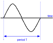
- One complete cycle as is shown above is completed in a time period of T in seconds
- The number of cycles completed in one second is the frequency f and the unit is Hz (Hertz)
- Thus T = 1 / f or time to do one complete cycle is one divided by the frequency in Hz
- And f = 1 / T or the frequency in Hz is given by one divided by the time T to do one cycle.
Example
If an RF signal has a frequency of 5MHz what is its periodic time ?
A 2ms, B 2u sec, C 200n sec,. D 2 sec
Answer
5MHz is 5,000,000 cycles in one second, so to find the period it is simply one second divided by the number of cycles. ( from T = 1/f )
1 / 5000000 = 0.0000002 or 200ns ( nano seconds
so correct answer is C
Recall the concept of phase difference between two signals, and that it can be expressed in degrees.
As well as measuring time in seconds it is also referred to as so many degrees. Have a look at the diagram below. Note the progression rotates anticlockwise
You can see that there are markings at the bottom of 0 - 180 - 360 which are measurements in degrees. There are 360 degrees in a circle (see diagram above) just as there are in one cycle of the sine wave.
Phase
The word phase is used in the context of the waveform to mean an amount of time. The amount of time to do one complete cycle is 360 degree and half a cycle 180 and so on.
Phase angle
Thus if two sine waves are on the same diagram but start and finish at different places the time difference between them can be expressed conveniently as a phase angle.
Out of phase
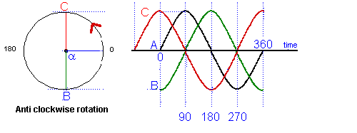
The amount that a curve lags or leads is given in degrees according to where the same point on the first curve the second one is. In the diagram above you can see that the angle α = 90o so by using the circle you could assess the amount of lead or lag in degrees./p>
From the point of view of the sine wave "A" at point 0, the wave form "C" is leading wave "A" by 90 degrees. If you look at the diagram above "C" as it was at the same point on the time line 90 degree earlier than "A".
Where as wave "B" lags wave "A" by 90 degrees as it has not yet reached the point on the time line where "A" is at 0.
All the waves "A", "B" and "C" are said to be out of phase.
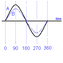
When trying to assess the amount of out of phase, the leading or lagging of one wave form to another you have to assess the location of the peaks that will indicate to you which wave form is ahead or behind and then consider where they respectively cross the ZERO line as here you will be able to use the graticule to count up the number of degree lag or lead.
In the diagram above the blue wave form is leading the green wave form and the amount of the lead would be assessed on the zero line where the two dotted red line indicate.
In phase
If two curves start and finish at the same time even though they have different magnitudes they are said to be in phase.
All of the above are difficult concepts so make sure you understand them before pressing on.
2E3 Recall that the potential difference
across and current through a resistor are in phase.
Recall that the power dissipated in a resistive circuit
varies over the cycle.
Recall that the RMS current or voltage in an AC circuit is
equal to the current or voltage of a DC supply that would
result in the same power dissipation.
Recall that the RMS value of a sinusoidal waveform, Vrms =
0.707×Vp (peak Voltage). Perform relevant calculations.
Recall that the term ‘Reactance’ describes the opposition to
current flow in a purely inductive or capacitive circuit
where the phase difference between V and I is 90°.
When dealing with D.C. the power dissipated in a resistive circuit is constant and one way it can be calculated is to multiply the applied voltage by the current flowing in the circuit. However when using an AC waveform the voltage is not constant but varies with the frequency. It follows that the current must also vary with the frequency of the applied voltage. Therefore the calculation of power dissipated in an AC circuit is not straight forward.
To calculate the power dissipated in an AC circuit the RMS (Root Mean Square) voltage must be used.
The RMS voltage is one that will the produce the same equivalent heating in the circuit as would an equivalent DC voltage. RMS voltage measurements can be assumed unless otherwise stated.
How do we calculate the RMS value of a waveform if we only know the Peak value (Vpk)
then √2 = 1.414
and 1 / 1.414 = 0.707 So RMS (Vpk x 0.707).......
Simple just multiply the peak value by 0.707
Recall that potential difference leads current by 90° in an inductor and that current lags potential difference by 90° in a capacitor.
However the voltage across the capacitor will lag the current by 900 and the voltage can be determined by V = I x Xc. Xcis the symbol for capacitive reactance and XL is the symbol for Inductive reactance measured in ohms
2E4 Recall that the ratio of the RMS potential difference to the RMS current as the capacitor stores energy in its electric field is called the reactance of the capacitor and is measured in ohms.
The
ratio of the AC voltage to the current flowing in the circuit
as the capacitor stores energy in its electric field is called
the Reactance of the capacitor and is measured in ohms.
Know that the reactance of a capacitor depends on the
frequency of the alternating current and that the reactance
falls as the frequency rises.
Identify the graph of reactance against frequency for the
capacitor.
Capacitance Reactance and that by an inductor Inductive Reactance, both have values in ohms.
 ,
in ohms, represents capacitive reactance in an AC circuit.
,
in ohms, represents capacitive reactance in an AC circuit.
 ,
in ohms, represents inductive reactance in an AC circuit.
,
in ohms, represents inductive reactance in an AC circuit.
In the formulae that may follow they use certain symbols :-
 = frequency
in Hz
= frequency
in Hz
 = inductance
in henries
= inductance
in henries
 = capacitance
in Farads
= capacitance
in Farads
 = 3.142
Capacitive Reactance
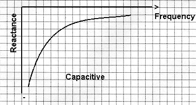
As we saw earlier at a.c. the voltage leads the current by 90 degrees. We have difficulty calculating the capacitive reactance due to at any one moment in a cycle they are both at different levels. In d.c circuits we use ohms law as R = V / I.
The way we overcome this in a.c. calculation is to use the RMS value. So now XC = VRMS / IRMS. The result is in ohms.
The origin of some of the text on this page is from the RSGB with additions by the web master