

2G1 Understand that a simple transformer consists of two coils of wire sharing the same magnetic field.
![]()
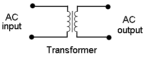
This is the circuit diagram which represents a transformer with an Iron core.
Recall that it may have an iron core to concentrate the
field.
An iron core concentrates the magnetic field
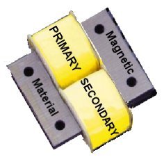
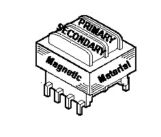
As the diagram shows, a transformer in its basic form has two separate coils of wire (two inductors), the primary and the secondary. The iron core is used to concentrate the magnetic field when an AC source is supplied.


Each winding must be electrically separate from the other and each coil of wire must have insulation between each turn so it is usual to use enamelled wire which provides suitably insulation between turns.
There are two configuration shown a side by side with a metal core and one above the other with a metal core. Each style provides the transformation of voltage when an AC current is applied.
Understand that at higher frequencies (e.g. RF and IF) a ferrite core, rather than an iron core, is used for improved efficiency.
Ferrite is a magnet compound usually made from Iron powder and other elements powdered, and bound together with a type of resin. At RF frequencies a ferrite core or rod will improve the efficiency of the transformer better than if it was wound 'air-spaced'.
Understand that energy is transferred from one coil to the other by changes in the field when alternating current is used, and that this does not happen with constant direct current.

ONLY an AC source can induce a magnetic field in the "primary" coil and this is transferred to the second coil due to the magnetic field and thus induces an AC in the second coil.
A DC source does not induce energy transfer from one coil to the other.
 So if I need Direct
Current (DC) to run my rig how do I get it ? By using a mains power supply
which addition to having a transformer to reduce the voltage from mains level
to near the output voltage level but it also has diodes that rectify the
AC and thus produce BUT that is covered in another section called Diode,
which is coming up soon if you are following this course in order.
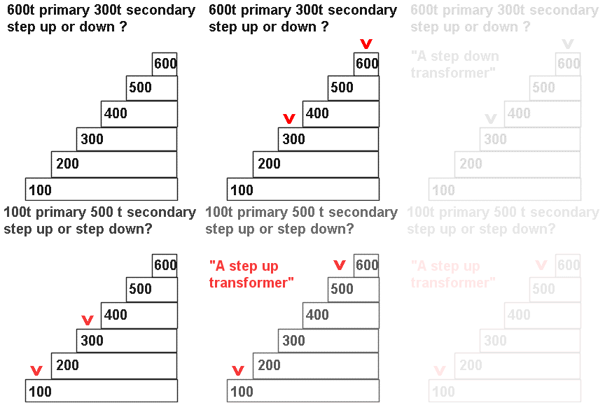
Understand that an alternating potential difference (such as the mains) can be stepped down using fewer turns of wire on the secondary coil than the primary and can be stepped up using more turns on the secondary than on the primary.
![]() Students are not
being able to recall that the transformer does not affect the Current passing
only the voltage being induced in the secondary from the primary windings.
It is thought that the confusion is stemming from the fact that it is called
AC or alternating current that is being applied where as it is the voltage
that is changing from positive to negative continuously.
Students are not
being able to recall that the transformer does not affect the Current passing
only the voltage being induced in the secondary from the primary windings.
It is thought that the confusion is stemming from the fact that it is called
AC or alternating current that is being applied where as it is the voltage
that is changing from positive to negative continuously.
In a mains power supply the AC mains voltage electricity is fed to a transformer's primary coils. This induces an AC voltage in the secondary either greater or less than the input voltage depending if the transformer is a step up (greater output voltage) or step down (lesser output voltage).

The transformer as a component itself can only step up or step down AC - it does not convert the AC to DC.
The mains AC potential can be "stepped down" by using fewer turns on the secondary than on the primary and this effect is used to provide a lower voltage AC in the early stage of a power supply prior to the other components.
Should there be a need to create a higher AC potential than mains AC this too can be achieved by using more turns on the secondary than the primary.
The animations should help you to remember step up and step down.

NB. The stepping up or down has nothing to do with the fuse rating in the primary or secondary windings should there be such items in the circuit.
Understand that the output from a transformer will always be an alternating current.
DC just does not work with transformers as explained above.
Note: Appreciation of the impedance change is not required.