

Technical aspects Part 1
Fundamental theory
2A1 Understand that the flow of electrons is an electric
current.
The ELECTRON
The word electronics comes from the word electron and an electron is defined in the "Oxford" dictionary as :-
An electron is a stable elementary particle with indivisible charge of negative electricity, found in all atoms and acting as carrier of electricity in solids.
 What that means to you and I is that the electron forms
the basis of all electrical theory and has a negative charge and therefore
is attracted to anything with a positive charge.
Recall that that a conductor allows electrons to flow easily and that an insulator does not.
Electrons can flow easily in some materials that are called conductors and not flow easily in others which are called insulators.
Recall that metals such as copper and brass are good conductors. Plastics, rubber, glass and ceramics are regarded as insulators.
An example of a conductor is a piece of copper wire and an insulator is plastic such as you often find around the out side of a wire so that your fingers are "insulated" from the wire carrying electrons.
Recall that a current can flow across wet insulators.
You
need to know that under certain circumstances "water" is conductive.
Only pure water is not a conductor as the water needs impurities such
as dust particles mixed in with it to make it conductive. Thus rain
water is not pure water as it has fallen through the atmosphere where
it has picked up particles of dust matter which allows it to be
conductive.
Recall that the unit of electric current is the Ampere (Amp).
We
now know from above that a flow of electrons is an electric current
and when it is measured with an Amp Meter the current unit is in
Ampere(s) or Amps.
Recall that the unit of electrical potential is the Volt.
Firstly what is "electrical potential" well to
give it its proper name "Electrical Potential Energy" which
provides the effort to move charged particles, the electrons round a
circuit.
The unit of Electrical potential is call the
Volt and is measured with a volt meter with one lead on the positive
electrical potential and the onter lead on the negative potential
and the flow of electrons is know as voltage.
Batteries have electric potentials that are noted on the side of the battery as a + positive and - negative and we will see more about that in due course. The larger the voltage the more electrons can be pushed round a circuit.
2A2 Recall that a circuit is needed to allow current to flow, and that circuit will include a source of electrical energy.
We touched on the word "Circuit" a moment ago
and the circuit need to be complete to allow a current to flow and the
circuit also need a source of electrical energy for instance a battery

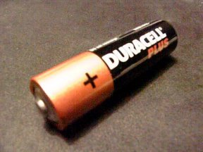
You and I probably think the the picture depicts a battery and to most people who are not in the electronics field would probably agree but in electronic terms the picture is of a single cell as it you broke it apart there would only be one + and one - connection.
A circuit is needed to allow current to flow.
To make a circuit we need several items :-
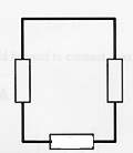
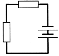
For there to be a circuit in which current will flow there must be an unbroken path between one battery terminal and the other.
What does each circuit have ?
 |
Battery Yes Resistance Yes Wire links Yes Links from one side of battery to another No - thus not a complete circuit in which electron (current) can flow. |
 |
Battery Yes Resistance Yes Wire links Yes Links from one side of battery to another No - thus not a complete circuit in which electron (current) can flow. |
 |
Battery No Resistance Yes Wire links Yes No battery thus no source of electrons thus not a complete circuit in which electron (current) can flow. |
 |
Battery Yes Resistance Yes Wire links Yes Links from one side of battery to another Yes - thus a complete circuit in which electron (current) can flow. |
|
The resistance could just have easily have been a light bulb symbol would have been used in place of the resistor symbol |
Recall that current in
all parts of a series circuit has the same value.
What
do we mean by a "series circuit". Well think of all the components as
a string of sausages in the one part link to another as only on place.

Above is a very simple Series circuit
which you first looked at up the page a little bit.
At any point in the circuit if you
broke the circuit and installed an ammeter and then made another
break and put in another ammeter and then a third one all the ammeters
would read the same value as the same number of electrons would be
flowing through each ammeter.
Recall that the potential differences across items in parallel are the same.
We have dealt with items linked in series as seen above but how are items connected in parallel.
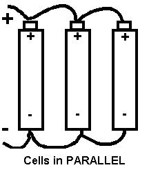
This is most easily shown in a picture of batteries connected in parallel.

The batteries have all
their + terminal connected and all the - terminal connected and they are
said to be connected in parallel. In fact any items which are similarly
connected such as resistors would also be call connected in parallel.
Because of the way they are connected the potential differences across items in parallel are the same.
The origin of some of the text on this page is from the RSGB with additions by the web master